Yachting Monthly
- Digital edition


Sailing in lightning: how to keep your yacht safe
- In partnership with Katy Stickland
- July 22, 2022
How much of a concern is a lightning strike to a yacht and what can we do about it? Nigel Calder looks at what makes a full ‘belt and braces’ lightning protection system

Storm clouds gather at Cowes, but what lightning protection system, if any, does your boat have for anchoring or sailing in lightning? Credit: Patrick Eden/Alamy Stock Photo
Most sailors worry about sailing in lightning to some extent, writes Nigel Calder .
After all, going around with a tall metal pole on a flat sea when storm clouds threaten doesn’t seem like the best idea to most of us.
In reality, thunder storms need plenty of energy, driven by the sun, and are much less frequent in northern Europe than in the tropics.
However, high currents passing through resistive conductors generate heat.
Small diameter conductors melt; wooden masts explode; and air gaps that are bridged by an arc start fires.

Sailing in lightning: Lightning is 10 times more likely over land than sea, as the land heats up more than water, providing the stronger convection currents needed to create a charge. Credit: BAE Inc/Alamy Stock Photo
On boats, radio antennas may be vaporised, and metal thru-hulls blown out of the hull, or the surrounding fiberglass melted, with areas of gelcoat blown off.
Wherever you sail, lightning needs to be taken seriously.
Understanding how lightning works, will help you evaluate the risks and make an informed decision about the level of protection you want on your boat and what precautions to take.
Most lightning is what’s called negative lightning, between the lower levels of clouds and the earth. Intermittent pre-discharges occur, ionising the air.
Whereas air is normally a poor electrical conductor, ionised air is an excellent conductor.
These pre-discharges (stepped leaders) are countered by a so-called attachment spark (streamer), which emanates from pointed objects (towers, masts, or lightning rods) that stand out from their surroundings due to their height.

Summer is the season for lightning storms in the UK. Here, one finds early at Instow, Devon. Credit: Terry Matthews/Alamy Stock Photo
This process continues until an attachment spark connects with a stepped leader, creating a lightning channel of ionised air molecules from the cloud to ground.
The main discharge, typically a series of discharges, now takes place through the lightning channel.
Negative lightning bolts are 1 to 2km (0.6 to 1.2 miles) long and have an average current of 20,000A.
Positive lightning bolts are much rarer and they can have currents of up to 300,000A.
Preventing damage when sailing in lightning
A lightning protection system (LPS) is designed to divert lightning energy to ground (in this case the sea), in such a way that no damage occurs to the boat or to people.
Ideally, this also includes protecting a boat’s electrical and electronic systems, but marine electronics are sensitive and this level of protection is hard to achieve.
Lightning protection systems have two key components: First, a mechanism to provide a path with as little resistance as possible that conducts a lightning strike to the water.
This is established with a substantial conductor from an air-terminal to the water.

Components of an external and internal lightning protection system. Credit: Maxine Heath
This part of the LPS is sometimes called external lightning protection.
Second, a mechanism to prevent the development of high voltages on, and voltage differences between, conductive objects on the boat.
This is achieved by connecting all major metal objects on and below deck to the water by an equipotential bonding system.
Without this bonding system high enough voltage differences can arise on a boat to develop dangerous side flashes.
The bonding system can be thought of as internal lightning protection.
Rolling ball concept
Lightning standards, which apply ashore and afloat, define five lightning protection ‘classes’, ranging from Class V (no protection) to Class I.
There are two core parameters: the maximum current the system must be able to withstand, which determines the sizing of various components in the system, and the arrangement and number of the air terminals, aka lightning rods.
Let’s look at the arrangement of the air terminals first. It is best explained by the rolling ball concept.
A lightning strike is initiated by the stepped leaders and attachment sparks connecting to form the lightning channel.
The distance between the stepped leader and the attachment sparks is known as the breakdown distance or striking distance.
If we imagine a ball with a radius equal to the striking distance, and we roll this ball around an object to be protected, the upper points of contact define the possible lightning impact points that need to be protected by air terminals.

Lightning protection theories and classifications rely on a ‘rolling ball’ concept to define requirements, areas of risk and protected areas. Credit: Maxine Heath
The air terminal will theoretically provide a zone of protection from the point at which the terminal connects with the circumference of the rolling ball down to the point at which that circumference touches the water.
The shorter the striking distance, the less the radius of the rolling ball and the smaller the area within the protection zone defined by the circumference of the rolling ball.
The smaller the protection zone, the more air terminals we need. So, we use the shortest striking distance to determine the minimum number and location of air terminals.
Class I protection assumes a rolling ball radius of 20m; Class II assumes a rolling ball radius of 30m.
Continues below…

Lightning: why we were struck
A personal investigation into how and why a catamaran was hit by lightning

‘Lightning destroyed the boat’s electronics’
Paul Tinley recounts a truly shocking lightning experience aboard his Beneteau 393 Blue Mistress and the subsequent insurance claim

Expert advice: boating emergency
A boating emergency is the sort of thing that everyone taking to the water should be prepared for even if,…

How batteries can explode – and how to avoid it
Marine electrical expert Nigel Calder explains why boat batteries emit hydrogen and how to minimise the dangers
Boat building standards are based on a striking distance/rolling ball radius of 30m (Class II).
For masts up to 30m above the waterline, the circumference of the ball from the point at which it contacts the top of the mast down to the water will define the zone of protection.
For masts higher than 30m above the waterline, the ball will contact the mast at 30m and this will define the limit of the zone of protection.
If Class I protection is wanted, the radius of the ball is reduced to 20m, which significantly reduces the zone of protection and, on many larger recreational boats, may theoretically necessitate more than one air terminal.
Protection classes
With most single-masted monohull yachts, an air terminal at the top of the mast is sufficient to protect the entire boat to Class I standards.
The circumference of the rolling ball from the tip of the mast down to the surface of the water does not intercept any part of the hull or rig.
However, someone standing on the fore or aft deck might have the upper part of their body contact the rolling ball, which tells us this is no place to be in a lightning storm.
Some boats have relatively high equipment or platforms over and behind the cockpit.

Protection classes to protect your boat while anchored or sailing in lightning
These fittings and structures may or may not be outside the circumference of the rolling ball.
Once again, this tells us to avoid contact with these structures during a lightning storm.
Ketch, yawl, and schooner rigged boats generally require air terminals on all masts, except when the mizzen is significantly shorter than the main mast.
The external LPS
The external LPS consists of the air terminal, a down conductor, and an earthing system – a lightning grounding terminal.
The down conductor is also known as a primary lightning protection conductor.
All components must be sized to carry the highest lightning peak current corresponding to the protection class chosen.
In particular, the material and cross-sectional area of the air terminal and down conductor must be such that the lightning current does not cause excessive heating.
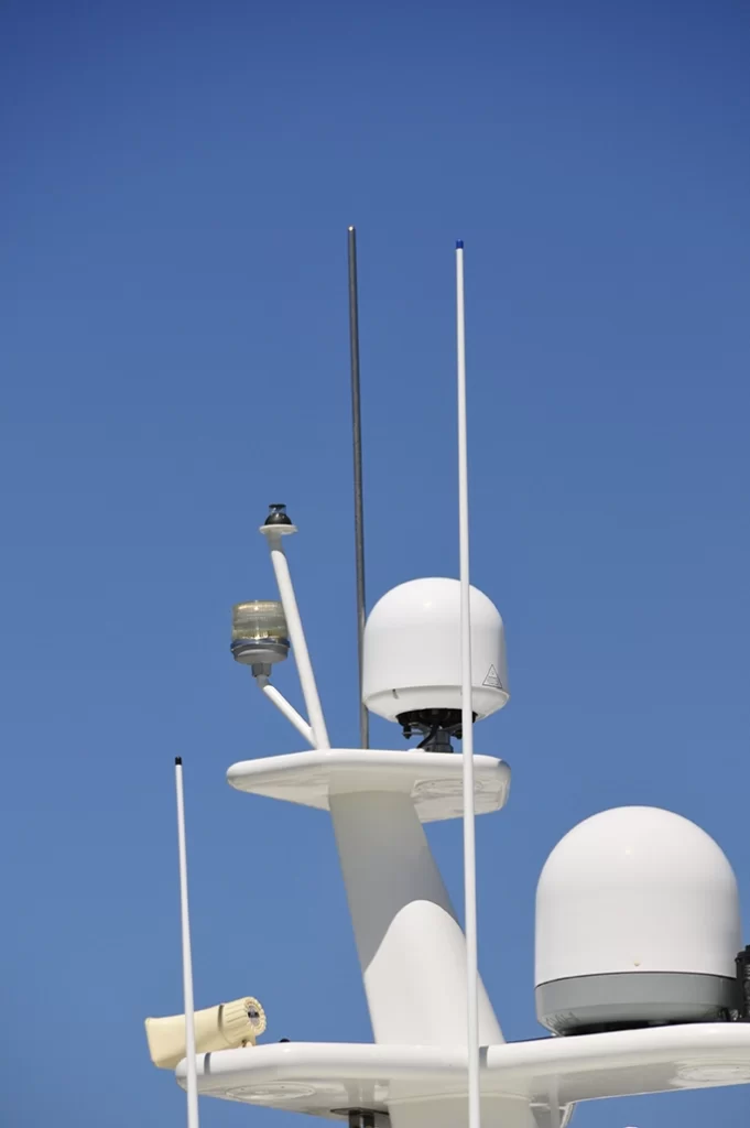
The air terminal needs to extend a minimum of 150mm above the mast to which it is attached.

A graph depicting NASA’s record of yearly global lightning events. The Congo once recorded more than 450 strikes per km2
It can be a minimum 10mm diameter copper rod, or 13mm diameter aluminum solid rod.
It should have a rounded, rather than a pointed, top end.
VHF antennas are commonly destroyed in a lightning strike.
If an antenna is hit and is not protected by a lightning arrestor at its base, the lightning may enter the boat via the antenna’s coax cable.
A lightning arrestor is inserted in the line between the coax cable and the base of the antenna.
It has a substantial connection to the boat’s grounding system, which, on an aluminum mast, is created by its connection to the mast.
In normal circumstances, the lightning arrestor is nonconductive to ground.
When hit by very high voltages it shorts to ground, in theory causing a lightning strike to bypass the coax – although the effectiveness of such devices is a matter of some dispute.
Down conductors
A down conductor is the electrically conductive connection between an air terminal and the grounding terminal.
For many years, this conductor was required to have a resistance no more than that of a 16mm² copper conductor, but following further research, the down conductor is now required to have a resistance not greater than that of a 20mm² copper conductor.
For Class I protection, 25mm² is needed. This is to minimise heating effects.
Let’s say instead we use a copper conductor with a cross-sectional area of 16mm² and it is hit by a lightning strike with a peak current corresponding to Protection Class IV.

Sailing in lightning: This catamaran relies upon cabling to ground from the shrouds but stainless steel wire is not a good enough conductor. Credit: Wietze van der Laan
The conductor will experience a temperature increase of 56°C. A 16mm² conductor made of stainless steel (for example, rigging ) will reach well over 1,000°C and melt or evaporate.
Shrouds and stays on sailboats should be connected into a LPS only to prevent side flashes.
The cross-sectional area of the metal in aluminum masts on even small sailboats is such that it provides a low enough resistance path to be the down conductor.
Whether deck- or keel-mounted, the mast will require a low resistance path, equivalent to a 25mm² copper conductor, from the base of the mast to the grounding terminal.
Grounding terminal
Metal hulled boats can use the hull as the grounding terminal. All other boats need an adequate mass of underwater metal.
In salt water this needs a minimum area of 0.1m². In fresh water, European standards call for the grounding terminal to be up to 0.25m².
A grounding terminal must be submerged under all operating conditions.
An external lead or iron keel on monohull sailing boats can serve as a grounding terminal.

This owner of this Florida-based yacht decided to keep the keel out of the equation when is came to a grounding plate. High electrical currents don’t like sharp corners, so a grounding plate directly beneath the mast makes for an easier route to ground. Credit: Malcolm Morgan
In the absence of a keel , the cumulative surface area of various underwater components – propellers, metal thru-hulls, rudders – is often more than sufficient to meet the area requirements for a grounding terminal.
However, these can only be considered adequate if they are situated below the air terminal and down conductor and individually have the requisite surface area.
Metal through-hulls do not meet this requirement.
If underwater hardware, such as a keel, is adequate to be used as the grounding terminal, the interconnecting conductor is part of the primary down conductor system and needs to be sized accordingly at 25mm².
Propellers and radio ground plates
Regardless of its size, a propeller is not suitable as a grounding terminal for two reasons.
First, it is very difficult to make the necessary low-resistance electrical connection to the propeller shaft, and second, the primary conductor now runs horizontally through the boat.
The risk of side flashes within the boat, and through the hull to the water is increased.

Sailing in lightning: GRP hull, fairing filler and iron keel will have carried different voltages during the strike – hence this damage
An engine should never be included in the main (primary) conducting path to a grounding terminal.
On modern engines, sensitive electronic controls will be destroyed in a lightning strike, and on all engines, oil in bearings and between gears will create resistance and therefore considerable heat which is likely to result in internal damage.
However, as it is a large conductive object, the engine should be connected to the internal lightning protection system.
Internal lightning protection
On its way to ground, lightning causes considerable voltage differences in adjacent objects – up to hundreds of thousands of volts.
This applies to boats with a functioning external lightning protection system but without internal protection.
Although the lightning has been given a path to ground along which it will cause as little damage as possible, dangerous voltages can be generated elsewhere, resulting in arcing and side flashes, threatening the boat and crew, and destroying electronic equipment.
We prevent these damaging voltage differences from arising by connecting all substantial metal objects on the boat to a common grounding point.

One of the holy grails of marine photography – a direct lightning strike on a yacht’s mast. Credit: Apex
The grounding terminal is also wired to the common grounding point.
By tying all these circuits and objects together we hold them at a common voltage, preventing the build-up of voltage differences between them.
All conductive surfaces that might be touched at the same time, such as a backstay and a steering wheel, need to be held to the same voltage.
If the voltages are the same, there will be no arcing and no side flashes.
The bonding conductors in this internal LPS need to be stranded copper with a minimum size of 16mm².
Note that there can be bonding of the same object for corrosion prevention, lightning protection, and sometimes DC grounding.
We do not need three separate conductors.
Electronic Device Protection
With lightning protection systems, we need to distinguish electric circuit and people protection from device protection.
Even with an internal LPS, high induced voltages may occur on ungrounded conductors (such as DC positive) which will destroy any attached electronics.
A mechanism is needed to short high transient voltages to ground.
This is done with surge protection devices (SPD), also known as transient voltage surge suppressors (TVSS) or lightning arrestors.

Marine-specific SPDs are few in number and domestic models are not suitable for boats
In normal circumstances these devices are non-conductive, but if a specified voltage – the clamping voltage – is exceeded they divert the spike to ground.
There are levels of protection defined in various standards depending on the voltages and currents that can be handled, the speed with which this occurs, and other factors.
This is a highly technical subject for which it is advisable to seek professional support.
Most SPDs are designed for AC circuits.
When it comes to DC circuits there are far fewer choices available to boat owners although there are an increasing number for solar installations that may be appropriate.
There is no such thing as a lightning-proof boat, only a lightning-protected boat, and for this there needs to be a properly installed LPS.

Nigel Calder is a lifelong sailor and author of Boatowner’s Mechanical and Electrical Manual. He is involved in setting standards for leisure boats in the USA
Even so, in a major strike the forces involved are so colossal that no practical measures can be guaranteed to protect sensitive electronic equipment.
For this, protection can be provided with specialised surge protection devices (SPDs).
The chances of a direct lightning strike on a yacht are very small, and the further we are north or south of the equator, the smaller this chance becomes.
It’s likely your chances of receiving a direct lightning strike are very much higher on a golf course than at sea.
‘Bottle brush’-type lightning dissipators are claimed by sellers to make a boat invisible to lightning by bleeding off static electrical charge as it builds up.
The theory rests upon the concept that charged electrons from the surface of the earth can be made to congregate on a metal point, where the physical constraints caused by the geometry of the point will result in electrons being pushed off into the surrounding atmosphere via a ‘lightning dissipator’ that has not just one point, but many points.
It is worth noting that the concept has met with a storm of derision from many leading academics who have argued that the magnitude of the charge that can be dissipated by such a device is insignificant compared to that of both a cloud and individual lightning strikes.
It seems that the viable choices for lightning protection remain the LPS detailed above, your boatbuilder’s chosen system (if any), or taking one’s chances with nothing and the (reasonable) confidence that it’s possible to sail many times round the world with no protection and suffer no direct strikes.
Whichever way you go, it pays to stay off the golf course!
Enjoyed reading Sailing in lightning: how to keep your yacht safe?
A subscription to Yachting Monthly magazine costs around 40% less than the cover price .
Print and digital editions are available through Magazines Direct – where you can also find the latest deals .
YM is packed with information to help you get the most from your time on the water.
- Take your seamanship to the next level with tips, advice and skills from our experts
- Impartial in-depth reviews of the latest yachts and equipment
- Cruising guides to help you reach those dream destinations
Follow us on Facebook , Twitter and Instagram.
An approach to a modern sailboat lightning protection system

We were lucky when we were struck by lightning on our small 35’ GRP cruising sailing boat in Turkey in 2013, but without an LPS. All the plastic and some of the metal gear at the top of the mast exploded (see photo below) and simultaneously the headlining in the saloon exploded downwards with a loud bang. So much smoke that we initially thought we were on fire; but my wife and I survived unscathed to tell the tale.
The most likely discharge exit was through the propeller shaft, but practically all electronics were violently destroyed and, as an electrical and electronic engineer, my assessment for our insurance claim afterwards showed that most devices had experienced severe arcing with small electronic components having exploded internally (see photo below).
An lightning protection system is a bonding, grounding and shielding arrangement made of four distinct parts: Air terminals, down conductors, a low-impedance ground system and sideflash protection.

The best lightning protection system cannot guarantee personal protection, or protection from damage to sensitive electronic equipment. Also it is not a lightning prevention system. I knew the private owner of one large blue water catamaran which has been struck three times in its life and it is not an old boat. Fortunately no one was hurt on any occasion, but many electronic systems on that complex boat were effected and had to be replaced on each occasion. Unfortunately catamarans are many times more likely to be struck than mono-hulls and records in the USA, where certain locations are particularly prone to electrical storms (e.g. Florida where boat ownership is high), show that mono-hull sailing boats are about 25 times more likely to be struck than motoryachts.
Lightning is very hard to study and to accurately predict its behaviour is almost impossible, but it is driven by the simple fact that a massive potential difference (voltage) exists between the highly charged clouds of a brewing thunderstorm and the surface of the Mother Earth. Eventually, a path is found through the atmosphere down to ground for some of the accumulated charge to discharge and the creation of a discharge path first requires the creation of so called ‘streamers’ [1],[2]. Bear in mind that air breaks down at 3 million Volts per metre, and you get some inkling of the enormous voltage differences involved.
In the middle of a large body of water, with your sailing yacht in it, the top of the mast, being the highest point around, looks like a handy point to discharge through. So the LPS is designed to control the first point of discharge and then make the onward path to ‘ground’ – in this case the sea – as direct as possible and capable of conducting very high currents for a very short time during the discharge.

In 2006, the American Boat and Yacht Council (ABYC) technical information report TE-4 [3], [4] recommended the following:-
• lightning protection system conductors must be straight and direct and capable of handling high currents. The main ‘down’ conductor is recommended to be 4AWG, or 25mm2 in European sizing; see diagram.
• A large enough area ground must be provided between the vessel and the water to offer an adequately low resistance path (ABYC recommends 1sq.ft. {0.1m2} in salt water; much larger in fresh water. NB this is not adequate for acting as the SSB counterpoise). Metal-hulled vessels naturally offer a large ground contact area with the sea, but the connection between the hull and all other electrical systems needs careful consideration.
• Heavy metal objects such as fuel tanks and engines must be bonded to the ground bonding arrangement to reduce the risk of ‘side flashing’ where the lightning literally can jump from one conductor to another, seemingly better path. Similarly, it can jump out of corners in cabling, so if bends must be made, then they should not be more than 90° and with as large a bend radius as possible.
The basic arrangement is as depicted in the diagram, where the ‘air terminal’ is a rounded end (circled in photo) metal wand mounted at the top of the mast to ‘attract’ lightning to it and, most importantly, to stand at least 6” (15cm) higher than anything else e.g. above the VHF or other antenna. Providing the air terminal is securely electrically bonded, presenting a high surface contact area, low resistance path to an aluminium mast, the mast itself can be used as the down conductor at least to the deck or keel, depending on where the mast is stepped. In the case of wooden, or carbon composite masts they present too high electrical resistance and a 4AWG cable must be run straight down the mast as the main down conductor. From the bottom of the aluminium mast or down conductor, the 4AWG onward path needs to be as direct and short as possible to the ground plate, or the metal hull.

It is actually better to leave through-hull metal fittings electrically isolated if they are already insulated from the rest of the boat by dint of their attached rubber or plastic hoses and their insulating mounting plates – decent quality bronze alloy seacocks and engine intake strainers will not unduly corrode if left submerged for extended periods of time without needing connecting to the vessel’s earth bonding. However, in the US it is more normal to bond everything metal below the waterline, use a tinned copper bus bar running the necessary length of the vessel, above any bilge water level, to connect each through-hull fitting to, which is then connected at one point only to the main grounding route out of the boat. This bonding arrangement is gaining in popularity outside the US with consideration of a lightning protection system.
Note in the diagram that all tie-ins, including fore- and back-stay (unless insulated) must use at least 6AWG (16mm2 European) cable. All large metal objects within 6ft (2m) of the lightning down path also need tying in with 6AWG (16mm2) cable. Examples are metal fuel tanks, main engines (despite them usually already being connected to the water via their prop shaft) and generators; this is to minimize the risk of ‘side flashing’ where lighting can literally jump from conductor to metal object, looking for a better path to ground, even if one does not exist.
In considering of the creation of a ground plate of sufficient size, a metal hulled vessel is ideal, but nevertheless only one electrical connection point to the hull should be made from the main 4AWG down conductor. This same point should have all the other earth bonding made to it alone. The DC main negative bus in turn should be connected to the earth bonding in only one place, though European boats generally have their DC system isolated from any bonding system to discourage DC earth faults, the US differs in this respect, preferring direct bonding. One solution to this dilemma is to use a suitably rated surge capacitor between the DC negative busbars and the bonding system for the LPS. In the case of a non-metal hulled sailing vessel, the attraction of using the keel as a discharge point should be resisted as it is in contact with the water some distance below the surface where already a lot is going on with respect to charge balancing, so an alternative point is likely to be sought out by the discharge, nearer the surface. It seemed clear to our very experienced (and ancient) marine insurance surveyor that, during our own strike in Turkey, the discharge was out through the propeller shaft.
So far, so good, but recent thinking and good practice [5],[6] has modified the above ideas to take into consideration the danger of side flashing much more. A side flash is an uncontrolled spark that carries current to the water and can do extensive damage to hulls and equipment. The good practice and standards for a lightning protection system relating to marine situations, such as they exist (see NFPA 780, latest version, especially chapter 8, ‘Protection for Watercraft’, [7]) are tending to treat a boat more and more like a building to exploit those well tried and tested techniques used in a land based situation. Rather than a ‘cone’ below the air terminal, the ‘zone of protection’ is now more reliably envisaged to be formed from a ‘rolling sphere’ of 30m radius, as shown below for a larger yacht [7],[8]:-

Diagram of Boat with Masts in Excess of 15 m (50 ft) Above the Water; Protection Based on Lightning Strike Distance of 30 m (100 ft).
With a large building, the down conductors from the various air terminals run down the outside of the building to a number of grounding stakes; not so with a yacht where, as we have described, we’ve now concentrated the discharge right in the middle of the boat, where the danger of side flashing into other metal parts is very real; if these parts are not bonded and protected by a properly designed, low impedance path there’s are very real further danger of the side flash finding its way onwards and out through the side of the boat to the surrounding water surface. This has indeed been experienced by an American friend of mine on a high-tech, all carbon racing sailing boat on its way back to Newport, which after being unavoidably struck several times in a violent storm, put in to New York and immediately hauled to find literally a thousand or more tiny holes around the waterline when the discharge had exited! Apparently lightning does not always take the straightest path to the water, but rather has an affinity for the waterline.
The latest version of this NFPA 780 standard recognises this danger and, in a departure from the older versions, provides for multiple grounding terminals to provide the shortest path to the surrounding water surface. These ‘supplemental grounding electrodes’ conduct lightning current into the water in addition to that conducted by a main ground plate. The new standard provides for a continuous conducting loop outboard of crewed areas, wiring and electronics. Placing the loop conductor well above the waterline, outboard, and with grounding terminals below it retains the advantages of an equalization bus, whilst correcting for its weakness with side flashes having nowhere else otherwise to go.

Protection of electronic equipment by a hermetic system on larger yachts
So much electronic equipment on board a yacht struck by lightning is very susceptible to permanent damage. The only safe way to fully protect electronic equipment is to have it completely disconnected from all other circuits when thunder and lightning are nearby, and I still to this day do that as much as possible, but how practical is complete protection really?
A recent idea I had whilst discussing the problem with a 30m ketch owner may have some merit, and I call it a ‘hermetic system’, so suggesting that it is sealed from the outside world: If the most critical and/or sensitive electronic equipment can be enclosed within its own quite separate power and cabling set, separate from the rest of the boat’s electrical and electronic wiring, then it is possible that it could be saved in the event of a lightning strike. One way to do this would be to run all those systems required to be protected effectively off an Uninterruptable Power Supply (UPS), powered from the AC bus (via the generator), then down converted to the necessary 24/12VDC electronics supply. In the event of a lightning storm, all AC connections to the UPS and any signals, power or ground returns outside the hermetic system must be open circuited by large clearance contactors. The electronics contained within the hermetic system can still continue to operate, for a limited time (depending on the capacity of the UPS batteries) and further choices can be made about what to shut down within the hermetic system to extend the battery life, leaving for example just the absolute minimum electronics to continue to safely navigate e.g. Depth, GPS, Chartplotter. Very careful consideration must be given to cable runs.
The VHF antenna on the main mast may be protected by a surge arrestor from one of several suppliers e.g. www.nexteklightning.com. No guarantee is likely to the effectiveness of this as a protection device in all cases of lightning strike and the manufacturers should be consulted for further information.
I certainly now resort to the marvel of a GPS chart plotter on my mobile phone when there’s a nasty electrical storm about and I’m out at sea! References: –
1. Top 10 best lightning strikes (USA) by Pecos Hank, with rare photo of an upward streamer. 2. http://marinelightning.com/index_files/SFMechanism.gif for a graphic showing the formation of negative streamers 3. ABYC (US) technical report TP-4 “Lightning Protection”. 4. Nigel Calder – “Boatowner’s Mechanical and Electrical Manual: How to Maintain, Repair, and Improve Your Boat’s Essential Systems” 5. “Complexities of Marine Lightning Protection”, By Ron Brewer, EMC/ESD Consultant, April 2011 6. “A New Concept for Lightning Protection of Boats – Protect a Boat like a Building” Ewen M. Thomson, Ph.D.; published in the October 2007 edition of Exchange 7. National Fire Protection Association (US) document NFPA 780-2014 “Standard for the Installation of Lightning Protection Systems” – see especially chapter 8 ‘Protection for Water craft’. 8. “Evaluation of Rolling Sphere Method Using Leader Potential Concept – A Case Study” P.Y. Okyere, Ph.D & *George Eduful – Proceedings of The 2006 IJME – INTERTECH Conference
Feature article written by Andy Ridyard. Andy Ridyard has been a professional electrical and electronics engineer for more than 35 years and started SeaSystems in 2008. His business is dedicated to providing troubleshooting, repair and installation services to superyachts internationally, specialising in controls and instrumentation. He lives with his wife in Falmouth, UK, but works mostly in the Mediterranean. SeaSystems has fixed countless intractable problems with marine control systems, marine electronics, Programmable Logic Controllers (PLCs) and marine electrical systems. For more information visit SeaSystems.biz .
Instagram Posts from the IIMS @iimsmarine
- Privacy Overview
- Strictly Necessary Cookies
- Performance & Marketing Cookies
This website uses cookies so that we can provide you with the best user experience possible. Cookie information is stored in your browser and performs functions such as recognising you when you return to our website and helping our team to understand which sections of the website you find most interesting and useful.
Strictly Necessary Cookie should be enabled at all times so that we can save your preferences for cookie settings.
| Name | Provider | Purpose | Expiration |
|---|---|---|---|
| wordpress_[hash] | WordPress | Used by WordPress to store your authentication details upon login and is limited to the admin area. | Just under 1 year |
| wordpress_logged_in_[hash] | WordPress | Used by WordPress to enable the interface to recognize you as a logged-in user and determine which account and preferences to use for various features. | Just under 1 year |
| wp-settings-{time}-[UID] | WordPress | Used by WordPress to facilitates customizing your view of the admin interface and the main site interface. The number UID is the individual user ID from the user database table. | 1 year |
| wordpress_test_cookie | WordPress | Used by WordPress to probe the ability of WordPress to set cookies. | 15 minutes |
| _grecaptcha | This cookie is set by Google reCAPTCHA, which protects the site against spam enquiries on contact forms. | 6 months | |
| m | Stripe | Used by Stripe Payment Services for fraud prevention and detection. | 400 days |
| __stripe_mid | Stripe | Stripe sets this cookie to process payments. | 1 year |
| __stripe_sid | Stripe | Stripe sets this cookie to process payments. | 1 year |
| wc_fragments_* | WooCommerce | Used by WooCommerce for eCommerce functionality. | 1 year |
| wc_cart_hash_* | WooCommerce | Used by WooCommerce to save items in a shopping cart. | session |
| woocommerce_items_in_cart | WooCommerce | Used by WooCommerce to save items in a shopping cart. | session |
| wp_woocommerce_session_ | WooCommerce | Used by WooCommerce for eCommerce functionality. | 2 days |
This website uses Google Analytics to collect anonymous information such as the number of visitors to the site, and the most popular pages. This also helps us optimise our marketing campaigns. User data sent to Google Analytics may be used for ad personalization and measurement of our ad campaigns. Keeping this cookie enabled helps us to improve our website.
Please enable Strictly Necessary Cookies first so that we can save your preferences!
| Name | Provider | Purpose | Expiration |
|---|---|---|---|
| _ga_* | Google Analytics | Contains a unique identifier used by Google Analytics 4 to determine that two distinct hits belong to the same user across browsing sessions. Accepting Marketing and Analytical Cookies allows us to use the data collected by this cookie for marketing and analytical purposes. | 1 year |
| _ga | Google Analytics | Contains a unique identifier used by Google Analytics 4 to determine that two distinct hits belong to the same user across browsing sessions. Accepting Marketing and Analytical Cookies allows us to use the data collected by this cookie for marketing and analytical purposes. | 2 years |
| _gid | Google Analytics | Contains a unique identifier used by Google Analytics to determine that two distinct hits belong to the same user across browsing sessions. Accepting Marketing and Analytical Cookies allows us to use the data collected by this cookie for marketing and analytical purposes. | 1 day |
| _fbp | Used by Facebook to deliver a series of advertisement products such as real time bidding from third party advertisers. | 90 days |
- Yachting World
- Digital Edition

Yacht lightning strikes: Why they cause so much damage and how to protect against them
- August 27, 2020
A lightning strike may sound vanishingly unlikely, but their incidence is increasing, and a hit can cause severe damage costing thousands of pounds, as well as putting an end to a sailing season, writes Suzy Carmody

Lightning strikes of boats are still fairly rare – but are on the increase. Photo: Image Reality / Alamy
Pantaenius handles more than 200 cases of lightning damage every year. “Over the past 15 years, the total number of such loss events has tripled in our statistics. The relative share of lightning damage in the total amount of losses recorded by us each year is already 10% or more in some cruising areas such as the Med, parts of the Pacific or the Caribbean,” added Pantaenius’s Jonas Ball.
Both UK and US-based insurers also report that multihulls are two to three times more likely to be struck by lightning than monohulls, due to the increased surface area and the lack of a keel causing difficulties with adequate grounding. Besides increased likelihood of being hit, the cost of a strike has also risen enormously as yachts carry more networked electronic devices and systems.

The CAPE index measures atmospheric instability and can be overlaid on windy.com forecasts
Avoiding lightning strikes
The only really preventative measure to avoid lightning is to stay away from lightning prone areas. Global maps of lightning flash rates based on data provided by NASA are useful to indicate areas of more intense lightning activity. They show that lightning is much more common in the tropics and highlight hotspots such as Florida, Cuba and Colombia in the Caribbean, tropical West Africa, and Malaysia and Singapore in south-east Asia.
Unfortunately, many of the most popular cruising grounds are located in tropical waters. Carefully monitoring the weather and being flexible to changing plans is an essential part of daily passage planning during the lightning season in high-risk areas. CAPE (Convective Available Potential Energy) is a useful tool for indicating atmospheric instability: you can check the CAPE index on windy.com (see above) as part of your lightning protection plan.
Protection against lightning strikes
Yachts that had no protection when lightning struck often experience extensive damage. The skipper of S/V Sassafras , a 1964 carvel schooner, reports: “Most of the electronics were toast. Any shielded wiring or items capable of capacitance took the most damage: isolation transformer; SSB tuner; autopilot and N2K network Cat 5 cables.”
Article continues below…

What is a Spanish Plume? Thunderstorms, lightning and downdrafts explained
Earlier this summer we saw considerable thunderstorm activity over the UK and Europe, resulting in flooding and some serious injuries.…

Expert sailing advice: How to handle a lightning strike on board
Lightning is the thing that scares me the most at sea. Having never experienced a lightning strike I think this…
The owner of Matador of Hamble , a Rival 41, recalls the effects of their strike: “The extent of the damage was not immediately obvious. For days afterwards anything with a semi-conductor went bang when we turned it on.”
The crew of Madeleine , a Catana 42S catamaran, had a similar experience. “We were struck in Tobago but only discovered the electrical damage to the port engine when we reached St Lucia and it was in the Azores that we found out the rudder post was broken and we had lost half our rudder.”
It therefore seems prudent that in lightning prone areas a protection system should be implemented where possible to protect the boat, equipment and crew. As a first step analysing the boat and the relative position of all the main metallic fittings can often reveal a few safe places to hide and places to avoid. Areas such as the base of the mast, below the steering pedestal and near the engine have the highest risk of injury.

Stays on a steel boat are attached directly to the steel hull. Photo: Wietze van der Laan / Janneke Kuysters
In terms of minimising the effect of a strike, one temporary method to limit the damage is to direct the current outside the boat using heavy electrical cables attached to the stainless steel rigging. With the other end of the cable immersed in the ocean, this provides a conductive path from the masthead to the ground.
The main flaw in this plan is that an aluminium mast has much greater electrical conductivity than stainless steel and is a more likely pathway to the ground. This system also requires adequate copper to be in contact with the seawater to discharge the current.
Other temporary measures include disconnecting radar and radio aerial cables, putting portable electronic items in the oven or microwave as a Faraday cage, turning off all the batteries or nonessential electronic equipment if at sea, or in a marina unplugging the shore power cord. All these procedures rely on someone being on board with several minutes warning before a strike to drop the cables over the side and turn off/disconnect and unplug.

Cable used as a down conductor from the shrouds on a catamaran. Photo: Wietze van der Laan / Janneke Kuysters
Posting an ‘Emergency Lightning Procedures’ card in a central location of the boat showing where to stand and what quick preparations to take is a simple first step.
Permanent lightning strike protection
In a thunderstorm, molecular movement causes a massive build up of potential energy. Once the voltage difference overcomes the resistance of the airspace in between, invisible ‘channels’ form between the base of the clouds and tall objects like masts, providing a path for a lightning strike to discharge some of the accumulated electrical energy. There will be less damage to a vessel if the discharge is contained in a well-designed lightning-protection system.
Lightning rods or air terminals installed at the top of the mast connected to an external grounding plate on the hull, via an aluminium mast, provide a permanent low impedance path for the current to enter the water. On boats with timber or carbon masts a heavy electrical cable can be used as a down conductor.
If not installed during production, a grounding plate can be retrofitted during a haul out. On monohulls a single plate near the base of the mast is adequate. A ketch, yawl or schooner requires a vertical path for each mast and a long strip under the hull between the masts, whereas catamarans usually require two grounding plates to complete the path to the water.
The current from a lightning strike is dissipated primarily from the edges of the plate, so the longer the outline the better. Warwick Tompkins installed a lightning protection system designed by Malcolm Morgan Marine in California on his Wylie 38 Flashgirl : “Two heavy copper cables run from the foot of the mast to the aluminium mast step, which was connected to a copper grounding plate on the outside of the hull via ½in diameter bronze bolts.”
The grounding plate was an eight pointed star shape. “Some liken it to a spider.” Warwick says, “And the very minimal electrical damage we experienced when struck was directly attributable to this spider setup.”

A copper ‘X’ grounding plate, used on boats that have a fin keel some distance aft of the mast. Photo: Malcolm Morgan Marine
Morgan adds: “Any cables associated with lightning protection should be routed away from other ship’s wiring wherever possible. For example, if the navstation electronics and main switchboards are on one side of the vessel, the lightning protection cables should be routed on the opposite side.”
An internal bonding circuit connects the major metal objects on a boat to the grounding plate via bonding cables. This can help prevent internal side strikes where the current jumps between objects in order to reach ground.
Morgan explains: “As modern boats are becoming increasingly complex careful consideration is required to ensure the bonding system is designed correctly. There are five possible grounding systems on a vessel (lightning protection, SSB radio ground plate, bonding for corrosion, AC safety ground, and DC negative) and all need to be joined at one common point and connected to the external grounding plate.”

This strike exited through the keel, blowing off the fairing and bottom paint. Photo: GEICO / BoatUS Marine Insurance
Surge protection
Yachts anchored close to shore or on shore power in a marina are susceptible to voltage surges during a thunderstorm. If lightning strikes a utility pole the current travels down the electricity cable looking for ground. It can enter a vessel through the shore power line or can pass through the water and flashover to a yacht at anchor.
Surge-protective devices (SPD) are self-sacrificial devices that ‘shunt’ the voltage to ground. They reduce the voltage spikes eg a 20,000V surge can be diminished to 6,000V but the additional current can still be enough to damage sensitive electronics. Therefore fitting ‘cascaded’ surge protection with several SPDs in line on critical equipment is a good idea.
High-tech solutions
Theoretically, if a lightning dissipator bleeds off an electrical charge on the rigging at the same rate as it builds up it can reduce or prevent a lightning strike. Lightning dissipators such as ‘bottle brushes’ are occasionally seen on cruising boats, though these are relatively old technology. Modern dissipators feature a 3⁄8in radius ball tip at the end of a tapered section of a copper or aluminium rod. The jury is out on their effectiveness.
A more high-tech solution is Sertec’s CMCE system, which claims to reduce the probability of a lightning strike by 99% within the protected area. The system has been widely installed on airports, stadiums, hospitals and similar, but has now been adapted for small marine use (and may reduce your insurance excess).
Arne Gründel of Sertec explains: “The CMCE system prevents a lightning strike by attracting and grounding excess negative charges from the atmosphere within the cover radius of the device. This prevents the formation of ‘streamers’, and without streamers there is no lightning strike.”

A Sertec CMCE marine unit, designed to dissipate lightning
- 1. Avoiding lightning strikes
- 2. ‘A lightning strike caused £95,000 of damage to my yacht’

- Center Consoles
- Dual Consoles
- Motoryachts
- Sport Cruisers
- Tenders & Ribs
- U.S. Atlantic
- Engine Buyers Guide
- Electronics
- Digital Edition

A Quick Comprehensive Guide to Lightning Protection for Boats
Understanding lightning mitigation for boats, techniques to lessen the impact of a lightning strike, adopting standardized lightning protection for boats, key components of a boat's lightning protection system: wiring, air, and ground terminals.
Also Read: Marine Electronics - Discover The Latest Award-Winning Products For 2023
-by steve d’antonio.

Fed Skips, Bull Runs Wild
Hello summer after a good six months, what’s next.

Leave a Reply Cancel reply
Your email address will not be published. Required fields are marked *
Save my name, email, and website in this browser for the next time I comment.
Receive our Newsletter

Recommended

Big Changes in Bahamas Travel as of November 1, 2020

Boating in New Orleans, Louisiana

Don't miss it

Volvo Penta’s Latest Marine Accessories For Improved Boating Experiences

Unstoppable! What Does the Fed Know That We Don’t Know?

International Boatbuilders: Discover Some of the World’s Best Yachts and Catamarans

Enjoy These 4 Delicious European-Inspired, Boat-Friendly Recipes While Cruising

Hurricane Boat Preparation: Tips You’ll Want to Safeguard Your Vessel

The Door is Open. Time for the Fed to Act. How Much?
- Terms Of Service
- Privacy Policy

1591 E. Atlantic Blvd, 2nd Floor Pompano Beach, FL 33060 Office: +1 (954) 522-5515 Fax: +1 (954) 522-2260 Contact us: [email protected]
© 2024 Southern Boating Media
- News & Views
- Boats & Gear
- Lunacy Report
- Techniques & Tactics
MARINE LIGHTNING PROTECTION: Getting Z-Z-Z-Zapped on a Sailboat

I have to admit I don’t normally think about this too much. As is true of many sailors I suspect, I have subscribed to the philosophy that lightning and its effects are so random and poorly understood that you can get royally screwed no matter what you try to do about it. Which is a great predicate, of course, to going into denial and doing nothing at all. But the death in Florida last summer of Noah Cullen , a most promising young man who presumably was killed in a lightning strike while out singlehanding on his pocket cruiser, got me pondering this in a more deliberate manner. On doing some research, I found there are some hard facts out there that are well worth knowing.
Much of what we tend to learn about lightning is anecdotal, which mostly serves to make it seem more mysterious. I, for example, have never been struck by lightning, but I did once cut through some severe thunder squalls in the Gulf Stream in a grounded fiberglass boat and saw a bolt of lightning the size of a large tree trunk flash straight into the water just a few yards behind us. I can’t begin to tell you why it didn’t hit our nice 55-foot aluminum mast, and ever since then I’ve believed a strike is pretty much an act of God. It’s either going to get you, or not, and there’s nothing you can really do about it.
I have met a number of sailors who have been struck by lightning, mostly in grounded boats, and in every case they told me they lost all their electronics. So I have also always assumed there is nothing you can really do to protect installed electronics from a lightning strike.
But you should forget all the anecdotes you ever heard, at least temporarily, and think about the following:
Likelihood of a strike: It’s probably much higher than you like to think. One source states that a sailboat with a 50-foot mast will on average be struck once every 11.2 years. According to insurance data, the general average for all boats is about 1.2 strikes per 1,000 boats each year. The average bill for damage is around $20,000. Most strikes are on sailboats (4 strikes per 1,000 sailboats each year). And these are likely lowball numbers, as it seems many lightning-strike victims are not insured or do not report the strikes to their insurers. According to one independent survey, unreported strikes could be as high as 50 percent of the total.
Location is also a big factor. Some areas, including very popular cruising grounds like Florida or Chesapeake Bay, are much more lightning-prone than others, and you are obviously much more likely to get struck when sailing within them. The overall average for reported lightning strikes on boats in Florida, for example, is 3.3 strikes per 1,000 boats each year, nearly three times the national average.
Map showing lightning strike probabilities around the world. The higher the number, the higher the probability
Interestingly, catamarans overall apparently are struck twice as often as monohulls. Could this be because they are effectively twice as much boat???
Preventing a strike: It really isn’t possible. There is no technology that can positively keep your boat from being hit. There’s seems to be little evidence, for example, that those silly little masthead bottle brushes some people put up are good for anything.
Spectacular image of a sailboat getting hit in Rushcutter’s Bay in Sydney Harbor, Australia, with inset images showing damage to the mast. Lots of other targets with masts around, so why did the bolt hit this one boat?
Limiting damage: This is where the action is. To paraphrase one writer: it is a fallacy to think in terms of “lightning protection.” What you want is “lightning control.” Which definitely means grounding your boat! An ungrounded boat is much more likely to suffer potentially disastrous damage when struck (i.e., holes in the hull, dead crew, etc.). A boat in fresh water is also much more vulnerable, because fresh water doesn’t conduct electricity as well as salt water. An ungrounded boat in fresh water is most vulnerable of all. If you’re on one of these during a strike, you may as well just forget about it and put a cap in your head.
Typical exit damage around an anchor well drain on a fiberglass boat. Hull damage just above the waterline is not at all unusual
Grounding your boat: The old school notion of leading a big copper strip from the base of your mast in a straight line to a single grounding plate on your hull is the process of being discarded in favor of a more sophisticated technique that connects the mast as primary conductor to a network of dissipating electrodes installed just above a boat’s waterline, the idea being in effect to make all of the boat’s hull something like a Faraday cage, so that the equipment and people within will be safer.
Example of a more modern grounding system
Note (I was particularly gratified to learn this): a metal hull is indeed a great ground, and the fact that it is painted, or coated in epoxy, or whatever, doesn’t change this. But you can still suffer significant damage on a metal boat!
Bonding: You and the gear on your boat are more likely to survive a strike without damage if the major bits of metal on your boat are bonded to the grounding system. This reduces the likelihood of dangerous side flashes. (It does, however, create complications with respect to the potential for galvanic corrosion on a boat.)
Saving electronics: First of all, stowing handheld electronics (or any disconnected electronics) in your oven will protect them during a strike. Just remember to take them out again before using the oven!
More importantly, you can protect installed electronics using various individual surge protectors, fancy spiral wiring, and other techniques I’m not going to pretend to understand, much less explain. See the sources below for more details.
Your personal safety: This should be most important, right? You want to stay off the helm if possible, stay below, stay dry, and don’t touch any big pieces of metal. All of which are easier said than done when you’re in the middle of a big squall! It would seem the most prudent tactic is severely reduce sail, or take it all down, pop the boat on autopilot, and get below well in advance of and after a thunderstorm.
Lightning and Sailboats : Academic paper published by Ewen M. Thomson, currently recognized as the most well-informed go-to guy on this subject.
Marine Lightning Protection : Website for a business run by Ewen Thomson (see above), who is a pioneer in modern cage-style boat-grounding techniques. Thomson will ground and bond your boat for you, if you like, but there’s also lots of useful raw info in here.
Lightning Survey Results : Discussion re results of a small independent online lightning-strike survey conducted by a cruiser who owns a power-cat named Domino . Very informative.
Considerations for Lightning Protection : Conclusions reached post-survey by the owner of Domino , referenced above.
Lessons in Lightning : Ocean Navigator article by a cruiser in an aluminum boat who was struck by lightning in the Baltic. Of particular interest to those (like myself) who own aluminum boats.
There are lots of other resources out there, but these four links are a very good place to start. You’ll find many other valuable sources just by reading through these articles and following the links within.
Related Posts

STORM PORN: Casco Bay Thunder Squall

We were hit by lightning in a fast moving front off Newfoundland many years ago (before gps). All the electronics were fried! The binnacle must have been demagnetized as it hopelessly spun in circles, giving us only a hand sighting compass to steer by. The smell of burned wire insulation in boat was overpowering. Luckily this is a rare occurrence and for the most part just bad luck!

@Robert: Interesting. In Bermuda once I met a tall ship, steel hull, that had been struck by lightning, and as a result the whole ship was magnetized. Which also kept their compasses from working properly. They were on their way to Norfolk, Virginia, to get degaussed.

I feel obligated to take issue with a fair bit of what’s been said above. Without writing a textbook, the following is best seen as “almost correct”. If you consider that the sky has a positive electrical charge and the sea a negative charge, grounding the boat and the mast gives them a negative charge. Hence as far as the lightning is concerned, the bonded mast raised the local sea level to mast top height. Lightning will tend to bridge the narrowest gap with the greatest electrical charge difference – so by grounding boat and mast, you have made them MORE vulnerable to lightning strikes, not less. In other words, NOT grounding the boat and mast will REDUCE your chances of being struck.
Tying an earth system into the keel bolts is not likely to result in loss of the keel, but it sure does constitute trying your best to do so. If the bolts are electrically weak they may act as a fuse and “blow” during a strike.
Making a Faraday shield form shown above does help mitigate the effects of the strike compared to a simple bonding of the mast to the keel in many situations, but it’s over-rated. In a big strike, lightning will try to follow a straight path and the energy contained in such a strike is often too great for a simple system to be effective. And it needs to be understood that either method makes the strike a whole lot more likely to occur.
A grounded mast does offer a degree of protection to a non-bonded electrical system in the boat underneath. There is what’s termed a “cone of protection” extending downwards at 30 degrees from the top of the mast. This is the standard system used in telecommunications.
The best protection you can have is to park your ungrounded wooden boat with a wooden mast and an electrical system isolated from the sea, right next to a grounded metal boat with a big aluminium mast. In the photo above depicting the Sydney harbour yacht being struck, the question was posed “why did the bolt hit this one?” The answer is that it was best grounded boat in that area.
@Bryan Tuffnell while part of what you say is true that a grounded boat is more likely to be struck the catch is that it will do less damage if struck where as a boat not grounded is less likely to be struck if it ever is you will have significantly more damage
Maybe, but quite likely not. The only way to offer lightning protection is to place a grounded lightning target above the mast, but electrically isolated from the mast and every other part of the boat. The grounding is completely independent of the mast, rigging, interior, electrical system, and above waterline areas of the hull. The idea is that this attracts the lightning and provides a low impedance path to ground, without drawing the charge into any part of the boat or its contents. Using this strategy one does not ground the mast, hull, rigging, etc. This is the only strategy to apply if one insists on lightning protection.

the sky has a positive electrical charge and the sea a negative charge
Its the other way round. When polarity builds up the negative charge is at the cloud base, and the positive at the sea surface. [quote=Bryan TuffnellNOT grounding the boat and mast will REDUCE your chances of being struck[/quote] Wrong – the enormous voltage actually doesn’t care if you’re grounded or not. Given the fact that the boats surface will always be wet or moist in some way it is “grounding” enough to raise the sea level polarity up to the mast top. The only thing proper grounding does is trying to guide the current of a charge in a way that does the least harm.
Not necessarily in the first case, and generally not true in the second… the polarity of lightning is variable, and there are countless examples of nearby strikes to ungrounded boats. Obviously if lightning didn’t care of you were grounded or not, lightning conductors wouldn’t work.
As far as doing the least harm goes, grounding the mast is about the worst thing you can do, particularly if you have grounded electrical items onboard.

Our boat (20′ cruiser) has no grounding system. Is it foolish to think that the method where a set of jumper cables is attached to mast and other end dropped overboard, might be a good emergency strategy if caught in elec storm?

what a topic indeed. to protect or not to protect, that is the question. simply do you use a brush type or spike type diffuser on your mast, do you protect for side strikes, or stay central with mast bonding.. im trying to find an answer like us all and so far , the answers all differ..
Leave a Reply Cancel Reply
Save my name, email, and website in this browser for the next time I comment.
Please enable the javascript to submit this form

Recent Posts
- BAYESIAN TRAGEDY: An Evil Revenge Plot or Divine Justice???
- MAINTENANCE & SUCH: July 4 Maine Coast Mini-Cruz
- SAILGP 2024 NEW YORK: Lifestyles of the Rich and Famous
- MAPTATTOO NAV TABLET: Heavy-Duty All-Weather Cockpit Plotter
- DEAD GUY: Bill Butler
Recent Comments
- Angela on GROOTE BEER: Hermann Goering’s Botter Jacht (Not)
- Gweilo on SWAN 48 SALVAGE ATTEMPT: Matt Rutherford Almost Got Ripped Off! (IMHO)
- Alvermann on The Legend of Plumbelly
- Charles Doane on BAYESIAN TRAGEDY: An Evil Revenge Plot or Divine Justice???
- Nick on BAYESIAN TRAGEDY: An Evil Revenge Plot or Divine Justice???
- August 2024
- January 2024
- December 2023
- November 2023
- October 2023
- September 2023
- August 2023
- February 2023
- January 2023
- December 2022
- November 2022
- September 2022
- August 2022
- February 2022
- January 2022
- December 2021
- November 2021
- October 2021
- September 2021
- February 2021
- January 2021
- December 2020
- November 2020
- October 2020
- September 2020
- August 2020
- February 2020
- January 2020
- December 2019
- November 2019
- October 2019
- September 2019
- August 2019
- January 2019
- December 2018
- November 2018
- October 2018
- September 2018
- August 2018
- February 2018
- January 2018
- December 2017
- November 2017
- October 2017
- September 2017
- August 2017
- February 2017
- January 2017
- December 2016
- November 2016
- October 2016
- September 2016
- August 2016
- February 2016
- January 2016
- December 2015
- November 2015
- October 2015
- September 2015
- August 2015
- February 2015
- January 2015
- December 2014
- November 2014
- October 2014
- September 2014
- August 2014
- February 2014
- January 2014
- December 2013
- November 2013
- October 2013
- September 2013
- August 2013
- February 2013
- January 2013
- December 2012
- November 2012
- October 2012
- September 2012
- August 2012
- February 2012
- January 2012
- December 2011
- November 2011
- October 2011
- September 2011
- August 2011
- February 2011
- January 2011
- December 2010
- November 2010
- October 2010
- September 2010
- August 2010
- February 2010
- January 2010
- December 2009
- October 2009
- Boats & Gear
- News & Views
- Techniques & Tactics
- The Lunacy Report
- Uncategorized
- Unsorted comments
Return to Peterson Cutter Lightning Protection Page
ACTIVE STORM TRACKER Hurricane and Tropical Storm Information Learn more
Service Locator
- Angler Endorsement
- Boat Towing Coverage
- Mechanical Breakdown
- Insurance Requirements in Mexico
- Agreed Hull Value
- Actual Cash Value
- Liability Only
- Insurance Payment Options
- Claims Information
- Towing Service Agreement
- Membership Plans
- Boat Show Tickets
- BoatUS Boats For Sale
- Membership Payment Options
- Consumer Affairs
- Boat Documentation Requirements
- Installation Instructions
- Shipping & Handling Information
- Contact Boat Lettering
- End User Agreement
- Frequently Asked Questions
- Vessel Documentation
- BoatUS Foundation
- Government Affairs
- Powercruisers
- Buying & Selling Advice
- Maintenance
- Tow Vehicles
- Make & Create
- Makeovers & Refitting
- Accessories
- Electronics
- Skills, Tips, Tools
- Spring Preparation
- Winterization
- Boaters’ Rights
- Environment & Clean Water
- Boat Safety
- Navigational Hazards
- Personal Safety
- Batteries & Onboard Power
- Motors, Engines, Propulsion
- Books & Movies
- Cockpit Confessions
- Communication & Etiquette
- Contests & Sweepstakes
- Colleges & Tech Schools
- Food, Drink, Entertainment
- New To Boating
- Travel & Destinations
- Watersports
- Anchors & Anchoring
- Boat Handling
- ← Safety & Prevention
Modern Lightning Protection On Recreational Watercraft
Advertisement
While you can't prevent a strike, there's a lot you can do to mitigate — or even prevent — damage.

A thunderstorm passing over a marina has the potential to cause expensive damage.
The recent advances in electrical and electronic systems have revolutionized recreational boating. Vessel operations have been simplified and the boating experience enhanced due to the integration of electronics into almost every onboard system, from navigation and communications to propulsion and maneuvering. Complex engine electronics known by various names including Engine Control Unit (ECU) and Engine Control Module (ECM) have increased performance and reduced emissions on modern engines. However, these advances have come at a cost. Many 21st-century boaters depend on electronic systems to navigate and maneuver their boats, and many modern engines will not function if their electronics are compromised. That makes modern mariners and their boats vulnerable to a lightning strike that damages these now mission-critical systems, potentially leaving the boat dead in the water without navigation or communications equipment.
Unfortunately, sensitive electronics on boats have become increasingly vulnerable to lightning strikes, yet lightning-protection systems have not kept pace. It's not that there haven't been significant advances in lightning science since Benjamin Franklin developed his theories on how to protect barns and livestock. The National Fire Protection Association, Underwriters Laboratories, and industries which are significantly at risk from lightning, such as telecommunications, wind generation, aviation, and fuel, have achieved consensus on the science of lightning protection and have embraced new protocols and practices. But the recreational boating industry has been slow to adapt those changes to the marine environment. There are at least three reasons for that.

There is no evidence from independent laboratories that these fuzzy lightning dissipators prevent strikes.
First, corrosion and motion on board boats, as well as limitations with respect to weight, space, and geometry, make lightning protection more challenging than in shoreside installations. Second, the mandate of the standards body for the industry, the American Boat & Yacht Council (ABYC), focuses on protecting life; protecting equipment has been a lower priority. Third, there has been strong disagreement between professionals about the best way to mitigate damage in a lightning strike and precious little data to support one point of view over another. The sometimes-raucous debate surrounding certain unproven lightning- protection devices and such theories as "fuzzy" lightning dissipation terminals and early-streamer emission terminals, as well as unorthodox placement of grounding terminals (a.k.a. grounding plates), have sharply divided the recreational boating technical community, all of which makes consensus on lightning protection difficult, if not impossible.
This lack of guidance is frustrating for those with boats at risk. While a runabout in Portland, Oregon, or a daysailer in Portland, Maine, may have little risk of lightning damage (see " Striking Lightning Facts "), larger vessels (particularly sailboats) in such lightning-prone areas as the Chesapeake Bay or Florida absolutely should be protected using the best technology available. Any marine-insurance adjuster can attest that the potential for loss on these vessels can be great. The National Fire Protection Association made some fundamental changes to the watercraft chapter of NFPA 780: Standard for the Installation of Lightning Protection Systems in 2008 that incorporate the thinking that has become accepted in other industries. While the recommendations in NFPA 780 have yet to be embraced by the recreational boating industry as a whole, understanding what it says — and why — may assist you in developing a lightning-protection plan for your boat.
Lightning 101
The simplest way to think of a lightning strike would be as a short circuit between the cloud and the earth. The earth and an active thundercloud have either a positive or a negative polarity with respect to each other, just like battery connections that can arc if they are not separated by a long enough air gap. Whether the positive charge is in the cloud or on the water may have great importance to a physicist, but matters little to the cow in the barn or the VHF radio antenna on the mast.
The important point is that the earth (or in our case, the water) contains an unlimited supply of positive and negative charges; it is the thundercloud that induces the charge concentration in the water. For example, if a large concentration of negative charge coalesces in a storm cloud over the ocean, a large concentration of positive charge is drawn to the very top surface of the water directly beneath it. (Opposites attract.) Since air is a good insulator, no electricity will flow between the cloud and the water unless the airborne charge loses altitude, moves close enough to the surface of the water, and the lightning jumps the gap. If an electrically conductive material, such as an aluminum tuna tower or mast, stainless steel rigging, or a long vertical copper wire, comes between the cloud and the water, then the gap that must be jumped becomes shorter. The boat short circuits the voltage, much like a wrench across battery terminals.
Because boats are built from electrically conductive components installed between the water and the areas aloft (masts, rigging, antennas, towers, support structures, electrical wiring), a lightning strike is inevitable if an active thundercloud containing electrical charges passes overhead at a low enough altitude. How much damage the lightning strike does to the boat depends upon how easily the electrical energy from the strike can find its way through the boat to ground. There will be a lot less damage if the discharge is contained in a well-designed lightning-protection system than if it takes a detour through the ship's wiring and sensitive electronics on its way out of the boat.
This is a basic concept that surprises many boaters: A lightning-protection system is not designed to prevent a lightning strike, but rather to provide a safe discharge path for the lightning. This is the only viable solution for lightning protection (short of going back to wooden ships, kerosene lamps, and sextants). The technology to prevent lightning strikes does not yet exist.
Still, there are devices out there claiming to do just that. Lightning dissipaters (LDs) look like metal bottle brushes or frayed paint brushes and are installed on the top of the mast. The hypothesis is that the numerous conductive points on the LDs safely dissipate accumulated charges so the lightning strike will not occur. As far as I am aware, not a single independent testing laboratory has confirmed the effectiveness of lightning dissipaters as lightning preventers.
Early-streamer emission (ESE) terminals have also gained traction in some circles. Fancy lightning rods often shaped like a torpedo that usually come with electronic circuitry, these are supposed to attract lightning better than a standard lightning rod (also called an air terminal), to ensure that the lightning strikes the grounding path rather than what is being protected. Once again, I am not aware of any independent studies validating the effectiveness of these devices.
Lightning-protection systems actually function by acting as the "best" short circuit between the cloud and the water, one designed to lead the lightning harmlessly to ground. The system accomplishes this in two ways: by attracting lightning away from more destructive pathways between cloud and ground, and by sending the charge around, instead of through, what it is protecting.
The first concept has traditionally been known as the "cone of protection" or the area protected by an air terminal from a strike. Traditionally, the cone of protection has been thought to include a circle centered on the base of the air terminal whose radius equals the height of the terminal and to extend from the top of the air terminal to the ground at a 45 degree angle. In fact, the length of the final jump that lightning takes before striking the air terminal is about 30 meters. Recent research suggests that the actual area protected can be defined by an imaginary sphere with this radius that is "rolled" up to the air terminal. All objects inside the imaginary sphere will not be protected by the air terminal, which means the area protected often differs in size and shape from the cone of protection model. Modern lightning protection for airports and power plants use the rolling sphere method and place air terminals so that the areas of protection overlap and include any sensitive equipment that would be damaged by a strike.
The second concept will be familiar to many as the Faraday cage. As early as 1836, Michael Faraday discovered that objects surrounded by metal were protected from lightning (explaining why we are safe from lightning while in our cars). Many old-school sailors have used Faraday's discovery to good purpose when they placed sensitive electronics in the oven during a lightning storm (with the oven off, of course.) This practice can be significantly updated by placing sensitive electronics in the microwave oven!
21st Century Lightning Protection
Benjamin Franklin pioneered lightning protection in 1749 with the invention of the lightning rod, and, when it comes to recreational boats, until recently, little has changed. Under his model, the lightning is attracted to the lightning rod (air terminal), which then passes the lightning current harmlessly to a submerged metaevent secondary flashes from these metal structures.

Air Terminals are shown in green; grounding plates with down, side flash, and equalization conductors in yellow; loop conductors in red; and catenary conductors in blue.
NFPA 780 draws much from the old-school system while incorporating improvements based on the modern understanding of lighting protection. While solutions will vary depending on the boat, let's talk about the basics.
Air terminals (lightning rod or Franklin rod) should be installed at the highest points of masts, towers, etc. On a sailboat a single air terminal could be bolted to the mast; on a sportfish it could be bolted to the tower and made to look like an antenna. This should be higher than anything you are trying to protect from a lightning strike, such as a VHF antenna.
A heavy electrical conductor should be connected from each air terminal directly down to a grounding point on the hull. In the case of a sailboat's mast, aluminum is a good conductor, so no separate wiring run needs to be installed. (Note that the wiring inside of the mast will be protected due to the Faraday effect.) An aluminum tower will work the same way on a sportfish so long as the legs are connected to an adequate grounding plate. Where no aluminum structure exists to act as a down conductor, a 4 AWG wire or larger should be run from the air terminal to the grounding plate in as straight a run as possible and well separated from other wiring.
The grounding point should be a corrosion-resistant metal plate installed on the exterior of the hull below the waterline. The plate should be at least one square foot in size and at least 3/16 of an inch thick. Research shows that most of the electrical discharge occurs along the edges, so a long, narrow plate, especially one with grooves cut in it, will be most effective at dispersing the charge. A new major point of contention is where to install the grounding plate, or plates. Some research indicates that a location at or near the waterline is by far the most effective solution. On a sailboat, the lead keel can be used as the grounding plate if the keel is not fiberglass-encapsulated or covered in fairing. If the mast is solidly keel stepped, there would be no need for a separate conductor from the mast to the keel. Metal rudders or propeller struts are also acceptable as grounding plates.
Protecting Electronics
Surge-protective devices (SPD) or transient voltage surge suppressors (TVSS) should be installed on all equipment that's mission critical, expensive, difficult to replace, and/or prone to lightning damage. Examples include the ECU/ECM, alarm systems, chartplotters, and instruments.

A bank of TVSSs protecting sensitive electronics.
TVSSs are the most exciting development in the field of lightning protection. These semiconductor devices provide protection by suppressing lightning-related voltage spikes. They are widely used in the telecommunications, wind generation, and avionics industries.
TVSSs are connected across the input terminals supplying voltage to a piece of equipment; they can be thought of as fuses that react to voltage instead of current. The TVSS is an open circuit as long as the supply voltage feeding the equipment is in the normal range. However, if a lightning strike causes a momentary voltage spike and puts, say 1,000 volts on a 120-volt device, the TVSS will "clamp" or short circuit 880 volts and convert it to heat. The excessive heat could, and probably would, damage the TVSS; but destroying a $250 surge arrestor to protect a $5,000 engine controller is good engineering.

Grounding plates should be long and narrow with groves cut into them to disperse the charge more efficiently.
Voltage surge protection would be prudent for engine controls, navigation systems, steering systems, and shorepower systems. TVSSs come in many voltage ratings, energy ratings, response times, and so on. Some are designed to protect whole distribution systems, while others are suitable for individual equipment protection only. A well-designed system includes cascaded protection, with extra protection on mission-critical and lightning-prone equipment, such as main engines and shorepower systems. The key to a reliable and cost-effective system is to ensure that appropriately rated devices are specified and properly installed. The best TVSS in the world will be ineffective if it is not connected properly.
Despite the best technology, there can still be challenges with an NFPA 780-based system, particularly when the system is improperly or only partially installed. For example, if the air terminal is installed lower than an adjacent antenna, it will not protect the antenna; in that case, the antenna cable carries the lightning current. Also, if the down conductor is connected to the bonding system rather than directly to a dedicated grounding terminal (ground plate), the lightning strike can energize the entire bonding system before discharging into the water. Another common mistake is to secure the lightning down conductor to other wiring. The high current from a strike through the down conductor can result in voltage surges in these adjacent wires, leading to additional damage in equipment that would otherwise be completely unaffected by the lightning strike.
In Conclusion
The recent revolution in marine electronics demands an evolution of our thinking on marine lightning-protection; equipment protection should be an important aspect of any modern lightning protection system. The knowledge and resources to safely transform this change in thinking into reality are readily available, both from the NFPA and industries also at risk from lightning. However, there are unique challenges on pleasure craft that are not addressed by others. These must be solved by sharing the experiences of lightning-protection systems and their effectiveness across the industry.
Related Articles
The truth about ceramic coatings for boats.
Our editor investigates the marketing claims of consumer-grade ceramic coatings.
Fine-Tune Your Side Scan Fishfinder
Take your side-scanning fishfinder off auto mode, and you’ll be spotting your prey from afar in no time
DIY Boat Foam Decking
Closed-cell foam flooring helps make boating more comfortable. Here’s how to install it on your vessel
Click to explore related articles
James Coté
Contributor, BoatUS Magazine
James Coté is an electrical engineer, ABYC Master Technician, Fire Investigator and Marine Investigator. He operates a marine electric and corrosion control consulting firm located in Florida. For more information, go to: cotemarine.net
BoatUS Magazine Is A Benefit Of BoatUS Membership
Membership Benefits Include:
Subscription to the print version of BoatUS Magazine
4% back on purchases from West Marine stores or online at WestMarine.com
Discounts on fuel, transient slips, repairs and more at over 1,200 businesses
Deals on cruises, charters, car rentals, hotel stays and more…
All for only $25/year!
We use cookies to enhance your visit to our website and to improve your experience. By continuing to use our website, you’re agreeing to our cookie policy.
- Pontoon Boats
- Personal Watercraft
- nauticalknowhow
- Nautical Knots
- Tools and Calculators
How to Protect Your Boat From Lightning

Of all the dangers you can face at sea, lightning is one that almost no boater considers. Lightning is not a threat in the eyes of most people. It’s considered rare and unusual. You need to get that thought out of your head as a boat owner. Lightning strikes are far more common than you might think.
They key to staying safe from lightning at sea is preparation. You need to use a little help gleaned from 19th century scientist Michael Faraday. He can keep you safe from the total destruction of your electrical systems and a potential fire.
How Common Are Lightning Strikes on Boats?
According to the insurance provider BoatUS , the statistics are very unexpected. Around one in 1000 boats get hit by lightning every year. If there are about 12 million registered boats in America. Knowing that allows the numbers to become a little more clear. That’s 12,000 boats every year getting hit by lightning. One in 1,000 odds are not very high at all.
It should come as no surprise that taller boats are more at risk. This is for the same reason you see lightning rods on tall buildings. Lightning wants to get to the ground as fast as it can. It is attracted to conductive materials. The closer those materials are to the source of lightning, the more at risk they are. So anything tall and metal is at the greatest risk. The top of the mast on a sailboat is, in effect, a lightning rod at sea. If a sailboat and a jon boat are side by side on the water, the lightning will hit the sailboat every single time.
Likewise, the bigger the target, the more likely lightning is to hit it. Swap out the sailboat in our example with a yacht. The jon boat is still much safer. Bigger boats have more conductive materials on them. They have their own electrical equipment, which creates an electrical field. More metal parts will attract lightning. And simply having more area exposed makes it more attractive to a stray bolt from the sky.
It’s also worth noting that a multi-hulled boat is at greater risk as well. BoatUS stats show a multi-hulled boat is twice as likely to suffer lightning damage. On the upside, this doesn’t hold true for pontoon boats. In fact, they have statistically fewer instances of damage than other boats. So if you’re really worried about lightning, maybe give a pontoon boat a second glance.
- By the numbers, you want to have a bass boat, a pontoon boat , or a runabout. In 2012 and 13, insurance policy claims for lightning strikes on those boats were the lowest. They had a 0.1 chance in 1,000 of a direct lightning strike. That’s about as impressive as it can get.
- Averaged across all boats, the rate of lightning strikes was 0.9 in 1000. We’ve rounded that up to 1 in 1,000. Not trying to make things look worse than they are, but it’s just easier to say it that way. The point is mostly the same.
- A trawler or a motoryacht have a 1.5 in 1000 chance of being hit by lightning.
- A monohull sailboat will bump your odds of being struck significantly. At this point they are 3.8 out of 1000. More than double a trawler, nearly 4 times the average, and nearly 40 times what a bass boat is facing.
- A multihull sailboat has a 6.9 chance in 1,000 of being hit by lightning strikes. That’s about a 1 in 144 chance. You need a lighting protection system of some kind to avoid this. It won’t prevent lightning strikes, but it can prevent damage.
Why Are Multi-Hull Boats More at Risk?
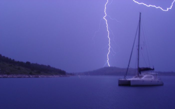
Why is a multi-hull sailboat a danger when a pontoon boat is not? That’s a good question and there is not a good answer. As frustrating as that may be, not enough research has been done. So it’s not easy to explain why a multihull sailboat is so much more at risk than other boats. Since pontoon boats are actually below average, the reason is not immediately apparent. That doesn’t change the fact that statistics bear this out, however. If you have a multihull sailboat, it is at the greatest risk of lightning strikes. That means you’ll want to be a little more cautious than you otherwise would be.
How Does Boat Size Affect Lightning Strikes?
It’s not just the kind of boat you have that can attract lightning. As we said before, size is a factor. Smaller boats offer a smaller conductive path. They offer less chance for lightning to reach ground. Because of that, they are less likely to suffer a lightning strike.
If your boat is fifteen feet or less then you can rest a little easier. Statistically speaking, it’s not likely to be hit by lightning at all. It’s not impossible, but the numbers are not even charted, really. You have a 0 in 1,000 chance. That could mean you still have a 1 in 10,000 chance, so don’t think you’re fully immune.
At 16 feet to 25 feet your numbers increase. There’s a 0.2 in 1,000 chance of any boat at those sizes being struck.
There’s a significant increase above 26 feet. From there up to 39 feet your odds are 2.1 in 1,000. A boat of that size will have a lot more conductive material present. It’s also going to have more electronics on board and you need to worry about that. Lightning strikes and electronics do not mix at all.
Finally, a boat over 40 feet have a 6 in 1000 odds of being struck by lightning.
The mast of a sailboat is hands down the most attractive part of a boat for lightning. If your mast top goes from 35 feet to 45 feet, you just increased the odds of a strike threefold.
Where Is a Boat Most at Risk from Lightning?
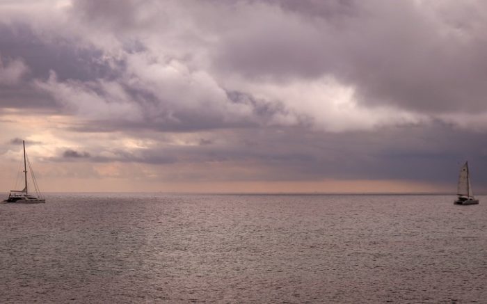
Weather can be a very fickle thing. Depending on where you are in the country you may endure lightning storms all the time. Other spots almost never see electrical storms. So it stands to reason not every part of the country is as potentially dangerous as others.
The frequency of lightning flashes across the country follows a fairly reliable path. Nowhere is “safe” from lightning, but there are high concentrations and low concentrations. In fact, you can nearly bisect the country in a diagonal. The northwest United States suffers the least amount of lightning strikes. So up the Pacific Coast into Washington. This is where you will find the lowest frequency of lightning strikes.
You can draw an arrow from that point all the way down to the southeast tip of Florida. Southern Florida has the highest frequency of lightning strikes. Florida is the number one state for lightning damage to boats. Let’s take a look at the list for the top 7 claims locations.
- Mississippi
- South Carolina
- North Carolina
Only one state there isn’t down towards the south-east part of the state. Maryland comes in tied with Mississippi thanks to its high density of sailboats. Something to keep in mind. Even when something seems safe, it doesn’t necessarily mean that it is.
Claims for lightning damage along the Pacific Coast happen rarely. The frequency is around 1 in 10,000. Given how low that is, it should give you pause when you think of the Atlantic Coast. All of the numbers we’re presenting are averages. That means there are a lot of west coast boats that are never being struck. Therefore, there are more east coast boats getting struck by lightning to balance things out. Keep this in mind if you boat anywhere along the Atlantic.
The Pacific Ocean is colder. That means lightning occurs less frequently on that coast. The Atlantic Ocean is much more fertile ground for storms.
What Can a Lightning Strike Do to a Boat?
Now that you know the odds of a lightning strike, what next? How bad could a lightning strike be? Well, it can get pretty ugly. A mild lightning strike will render any fixed electronics useless. Radio , lighting, GPS , bilge pump , engines, you name it. Generators will likely be fried in most cases. It’s not unheard of for a DC solenoid to literally melt.
It’s possible your engine will still run after a lightning strike. But this is like a deer still running after it gets hit by a car. It can happen, but it’s not pretty. It also may not run for long. Expect frequent misfires if it’s still operational. Also, a lot of smoke. Your RPMs are going to drop significantly. Fire risk will greatly increase. The chances of it failing anytime thereafter are very high.
Other systems may continue to function but not in the intended way. We’ve heard of bow thrusters that will continue to run. The problem is you can’t turn them off and they may only run hard to port or starboard. Changing direction is no longer an option.
Suffice it to say lightning can utterly ruin your electronics. More than that, it can wreak havoc with your boat’s body. Most of the metal and writing in a boat is designed with a certain charge in mind. The average lightning bolt is 300,000 million volts and 30,000 amps. It has a negative charge and is DC current. Think of what kind of battery your boat runs on. Is it 12 volt? Maybe 24? No matter what it runs on, it’s not meant to handle lightning level power.
When lightning hits your boat, it’s going to follow the path of least resistance. Unfortunately, lightning can also make use of something called electromagnetic induction. That means if you have two wires near each other, the electrical charge can jump from one to another. Even if the second wire is not touching the first through which the current is flowing. Just being close enough to it allows the power to arc and continue on its path. Your boat is going to be small enough that the lightning is able to continue on a path. It will travel through wires and across metal fittings and fixtures.
Much of the wiring in your boat is likely to be melted completely by lightning. The power flow can actually blow a hole right through your hull. It’s also possible that it will burn the fiberglass around metal fittings. That can create holes and cracks and cause a boat to sink.
Boats on the water typically suffer less damage than those on trailers or stored out of water. On dry land, the electricity will follow a path down to whatever is holding the boat up. On some boats you can even see the scorched path and burn marks along the hull. In the water, the power dissipates more evenly. It will cause less destruction as it reaches ground. In this case, of course, ground is actually water. Lightning protection systems are therefore important in preventing this.
The Cost of Lightning Strikes
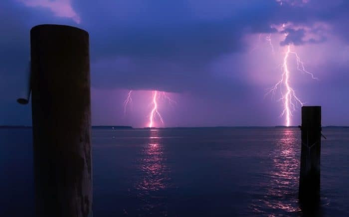
So what does all that damage do to a boat? More than 75% of all lightning strike claims are for less than 30% of the insured value. Of those damage claims, the vast majority of them are claiming electronics damage. That’s why, if you see a storm coming, it’s good to unplug those electronics that you can.
All of this being said, you need to keep things in perspective. You already know the odds on even getting hit by lightning in the first place. Suffering severe damage is still a rarity even when lightning strikes do occur. But the fact is it can happen, so you should be prepared. That’s where Michael Faraday and his Faraday Cage.
What is a Faraday Cage?
Michael Faraday created what is the basis for a modern lightning protection system. Lightning strikes can’t be prevented. They can be redirected, though. Faraday was convinced he could make a cage of conductive materials. The outside of the cage would redirect the electrical charge. This, in turn, would protect whatever was in the cage. You may have seen these before in YouTube videos.
The idea is to have this cage of conductive materials around a person or thing. All the metal is bonded together and carries the same electrical potential. Lightning follows the cage to the ground because it’s the path of least resistance. It’s like a bundle of lightning rods fused together. The electrical current can easily travel from the sky to the ground along it.
Obviously you’re not putting a literal cage around your boat to protect it from lightning. However, the same principles are used to protect your boat.
What’s the Best Lightning Protection System for a Boat?
In order to protect your boat from lightning strikes you need a way to redirect those strikes. Your cage is not a literal one but it does require certain conductive materials. You’ll need a marine electrician’s help here. They can put together the best protection system for your particular vessel.
In general, it works like this. Heavy conductors are used to create a cage by bonding all of your boat’s metal components. This starts at the top of the mast and must include all of the major components we have mentioned. Outriggers, railings, arches make a good framework. The AC compressor, engines, stove and other electronics need to be included as well.
A low resistance wire can connect all of these components and offer a path for the lightning to travel. The current will travel to ground, or in this case water, along the path. It can exit the boat through the propeller shaft or keel bolts. Ideally, though, you want a separate system in place. At least one square foot in diameter external ground plate is ideal. The electrical current can be routed to the ground plate and avoid damage to the rest of the boat.
Your engines should be bonded. This helps you avoid something called side flashes.
What is Thompson’s Lightning Protection System?
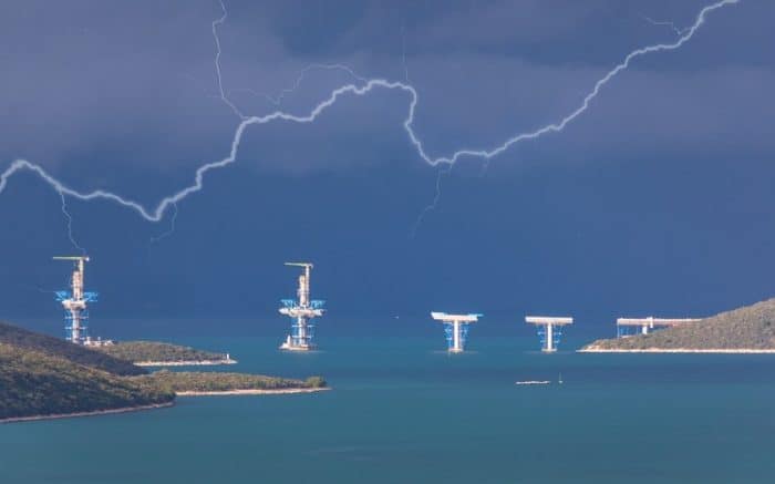
The National Fire Protection Association helped devise a system. Along with the American Boat and Yacht Council, they created this method. It was devised by Electrical engineer Ewan Thompson. He developed it as the best way to protect a boat from lightning.
- Start with lightning rods. A single rod protects in a cone of about 45-degrees. You want more than that, of course. Several lightning rods set up around a boat provide maximum lightning protection. Thompson found that the best lightning rod is a ½ inch in diameter with a rounded top. Located at the bow, the stern, and above the highest points can help create the basis of your cage.
- The rods need to be connected with heavy two-gauge wire. The wire needs to travel the easiest path to the water’s surface. If there are bends, they need to be long, sweeping ones. Remember, the current could potentially leap from one wire to another. This will happen if they are too close together. Run them outboard and keep them two feet away from any other wires. This is especially important if they are on parallel paths. Any closer and you risk electromagnetic induction. Then all your hard work will be for nothing.
If there is a point where your lighting wires cross normal wires, make it a right angle. Induction has the least chance of happening at right angles. It keeps the contact to the bare minimum.
- Rails and aluminum supports for a hardtop can become part of the cage. Bridge any gaps with wire, however. If the wire doesn’t connect gaps in rails, it can’t work.
- Create your Faraday Cage. You have the top of your cone of protection set up now. But to make it a cage you need one continuous band around the entire boat. This can be either one wire or a metal strap. It should be located below the level of the deck but above the waterline. Some manufacturers of boats include these bands right in the hull. Just above the waterline you’ll find a copper band around the entire boat. All the wires can be connected to it to dissipate any lightning strikes.
- Thompson’s method also includes the use of sparking electrodes. These small devices can be affixed around the boat above the waterline. They’re made from stainless steel or graphite and other fire-resistant materials. They allow the current to discharge into the water. When lightning does strike, it will typically blow them out so they will need to be replaced. It’s recommended they be placed most frequently near the bow. That’s where the majority of lightning strikes seem to occur.
- To avoid that side flash on your engine, you need to run more two gauge wire. Connect it to where the bonding system connects the engine. From there it can go to the electrodes. Also it can be connected to submerged grounding strips above and outboard of the prop. This is a better solution than letting the propeller take the electrical charge. You can also connect bow thrusters in this manner. When this is done properly, your thrusters and engines are all part of the cage as well.
Finally, use surge protectors. These are especially useful for your GPS and VHF radio . They can suppress voltage above 300 volts. As we’ve seen, that would be pretty important in a lightning strike. The result is knowing your expensive electronics can be protected.
How to Handle a Lightning Storm on a Boat

So, let’s say you have your boat all set up now. There’s a Faraday Cage, and you have your cone of protection. There’s a storm brewing and you can see lightning in the distance. Are you safe to wait it out? Maybe. But don’t risk it.
If you ever have the option, leave. Outrun a lightning storm whenever it is feasible to do so. Running for protection is always better than facing lightning in the open water. If that is not an option, then do your best to prepare. Make sure you pull in any fishing lines and bring in any swimmers if possible. Lightning can actually strike up to one mile ahead of a storm.
Turn off any electronics that you don’t need and stay low and centered in your boat.
What to Do If You Think Your Boat Was Hit?
Many lightning strikes are going to happen when you’re not there. Your boat will be in the marine while you’re at home. You’ll get to the boat and realize things aren’t working. The fridge is off, the radio is a no go, nothing that runs on power is turning on.
You have a few steps you should follow. These will allow you to give your vessel a thorough check after a suspected lighting strike.
- Turn off all of your battery switches
- Unplug shore power to prevent the possibility of a short circuit
- Check your bilge . If the bilge isn’t dry you may have an issue below the waterline and you’ll want to have the boat hauled out.
- You’ll need to call your insurance company once your boat is secure. If you know it’s not taking on water a haul out may not be necessary.
- Keep any damaged electronics or parts. The insurance company will want to assess them before they get tossed out.
- A marine surveyor can come and assess your boat. They’ll be able to determine what works and what has been destroyed. If the insurance company deems it necessary, they may pay for a haul out as well. That way everything below the waterline can be inspected.
The Bottom Line
Lightning damage is definitely a rare thing. But on the water it’s a lot more common than most boaters realize. It’s not the sort of thing you need to lose sleep over, but you should be prepared. Lightning protection systems are invaluable. You don’t want to be on the wrong end of a lightning strike one day. The saying “better safe than sorry” definitely applies here. If you have a sailboat, consider protection. Likewise if it’s a large boat, or one on the Atlantic coast anywhere. An ounce of prevention is worth a pound of cure.
My grandfather first took me fishing when I was too young to actually hold up a rod on my own. As an avid camper, hiker, and nature enthusiast I'm always looking for a new adventure.
Categories : Boats , nauticalknowhow

Paul on August 4, 2021
…”lightning hits your boat, it’s going to follow the path of least resistance. Unfortunately, lightning can also make use of something called electromagnetic induction. That means if you have two wires near each other, the electrical charge can jump from one to another. Even if the second wire is not touching the first through which the current is flowing. Just being close enough to it allows the power to arc and continue on its path.”…
The article is very informative but misses out some stuff & is possibly misleading in parts.
Arcing between wires is not electromagnetic induction. Electromagnetic induction is due to the fact that a lightning strike consists of repeated sharp rises & falls in large currents which produces an RF effect which creates rapidly changing magnetic fields which results in induced voltages in cables intersected by the changing magnetic fields.
One of the basic methods of protecting electrical & electronic equipment is to have twisted pair cables, mu metal cable shielding, arranging for most cable runs to be as horizontal as possible with all vertical runs in one place In heavy magnetic shielding conduits and ensuring that lightning current is always as vertical as possible. All mast cables should be connected by easy to reach & disconnect plug & sockets that can quickly be unplugged if needed.

Ben on August 23, 2021
What about galvanic considerations?

Chuck Dickey on September 2, 2021
So should you unplug shore power before a lightning storm?

Jeffrey M Streib on February 13, 2023
What effect might a lightning strike have on:
-The batteries and their capacity -Speakers
I suffered a lightning strike and lost almost all electronic components, engine components, gps, vhf steer by wire etc.
The insurance company has been good overall, but the surveyor doesn’t think the (3) batteries speakers, and bilges were related to the strike. (They all worked fine prior)
Any help would be appreciated.
Leave a Reply Cancel reply
Your email address will not be published. Required fields are marked *
Save my name, email, and website in this browser for the next time I comment.
More in Boats
What Is A Gunwale?

131 of the Best Hawaiian Boat Names
167 Patriotic Boat Names
The 138 Best Boat Names for Dog Lovers

The People’s Poncho Review and Ratings
Oru Lake Kayak Review
About Boatsafe
Established in 1998, BoatSafe is your independent guide into the world of boating, fishing, and watersports. We provide expert insights and detailed guides to help you find products tailored to your needs and budget.
Contact Boatsafe
- Address: 4021 West Walnut Street. Rogers, AR 72756
- Phone: (479)339-4795
- Email: [email protected]
Site Navigation
- How We Test
- Corrections Policy
- Privacy Policy
- Terms & Conditions
- Editorial Policy
- Affiliate Disclosure
Our Reviews

All content is © Copyright 2024. All rights reserved.
Please verify you are a human
Access to this page has been denied because we believe you are using automation tools to browse the website.
This may happen as a result of the following:
- Javascript is disabled or blocked by an extension (ad blockers for example)
- Your browser does not support cookies
Please make sure that Javascript and cookies are enabled on your browser and that you are not blocking them from loading.
Reference ID: 046092c4-7d40-11ef-bbdd-31185ac2667c
Powered by PerimeterX , Inc.
- Forums New posts Unanswered threads Register Top Posts Email
- What's new New posts New Posts (legacy) Latest activity New media
- Media New media New comments
- Boat Info Downloads Weekly Quiz Topic FAQ 10000boatnames.com
- Classifieds Sell Your Boat Used Gear for Sale
- Parts General Marine Parts Hunter Beneteau Catalina MacGregor Oday
- Help Terms of Use Monday Mail Subscribe Monday Mail Unsubscribe
Lightning Protection
- Thread starter captcoho
- Start date Apr 9, 2022
- Forums for All Owners
- Ask All Sailors
After reading older and not so old threads, how many sailors favor grounding their mast and rigging ?

Captain Larry-DH
I grounded my mast and rigging on my last boat. It was struck twice in 11 years. No hull damage, but a few rigging fittings showed scorch marks and were replaced as a precaution. Extensive electrical damage throughout the boat, both times. Melted VHF antenna both times. Does it attract lightning if you ground? Maybe. I can’t find anything conclusive on that question. I’ve heard of ungrounded boats that were struck too. I think a clear path to ground helps limit extent of damage if you’re struck, so I favor it for that reason. My new boat will be more challenging to ground, due to wire runs (catamaran) but I’ve already installed the Dynaplates. Connection on port side doesn’t have a path that can be totally hidden in unfinished areas, so I’m still thinking that one through. PS - Dynaplates do not explode from a direct strike. I’ve proven that by experience, twice. (I’ve read it on the web based on the theory that the porous metal can explode from internal steam pressure build up. Hogwash.)
I don't. The fact that lightning is so powerful and unpredictable that it is deemed to strike where it may defies any attempts to control it. There are unproven theories about factors that may prevent or attract lightning strikes and increase or diminish the damage but the data does not support any. I have opted to observe the data regarding lightning strikes on boats and use this data to try to try and minimize the occurrence of a strike. A good and well stablished statistical fact is that the occurrence of loss of life due to a lightning strike on a sailboat is nearly nil year after year. (the same cannot be said for Golf Courses) That alone has removed any fear from sailing near lightning. Another statistical fact is that the majority of lightning strikes occur near land as opposed to open waters. I only really care about the boat getting hit by lightning if I am aboard; as when it is docked and unattended it will be protected by insurance. When sailing I will steer the boat away from land. It is also prudent to get away from a lee shore in the accompanying storm conditions. There are a few theories about "cone of protection", grounding the mast, installing diffusers but they are all at best unproven. Seems to me that the cone of protection and grounding of the mast are mutually exclusive as grounding may seem to attract lightning instead of repelling it. Both theories remain unproven so it would be a personal matter of choice as to which to follow by faith. Very fortunately, remember the odds against getting hurt are very favorably on our side.

I do. My thinking is that a lightning strike is going to find the most direct way through the boat to the water. Either through a planned ground connection or possibly right through the hull, which could sink the boat. Either way, the electrical system and electronics would be fried, and fire is still a possibility from that, but providing a direct path to the water seems logical to me to minimize damage. As an architect, every tall building I designed was grounded with lightning rods, a proven invention we owe to Benjamin Franklin. An aluminum mast is effectively a lightning rod and the upper portion of Franklin’s system. It needs to be grounded as directly as possible to the water.

We are fabricating a new 1/8" x 1.5" stainless steel grounding connector now to attach to one of our keelbolts.
PaulK said: We are fabricating a new 1/8" x 1.5" stainless steel grounding connector now to attach to one of our keelbolts. Click to expand
Dalliance said: Mine may be a similar, less robust, approach. I have a copper ground wire from the aluminum mast base, down the compression post, to a stainless steel keel bolt almost directly below. External lead keel. Liberal application of Lanocote at the dissimilar metal connections. Click to expand

SBO Weather and Forecasting Forum Jim & John
captcoho said: how many sailors favor grounding their mast and rigging ? Click to expand

I favor having the rigging grounded. A number of years ago a physicist friend of mine said a grounded boat is more likely to get hit, but less likely to suffer catastrophic damage. I don't know how reliable that info is, but I still go by it. My understanding is that lightning does not seek out a target. When it is ready to discharge it does so immediately through the least resistant path. So if that discharge moment occurs a hundred feet from your boat, chances are your 60 foot mast is not the most direct path. Additionally, the rigging provides the crew protection as, I think, it forms a Faraday cage. This is often referred to as the "cone of protection" referred to in Power Squadron materials. If you cruise or distance race you are going to get caught out in lightning at some point.
Dalliance said: I do. My thinking is that a lightning strike is going to find the most direct way through the boat to the water. Either through a planned ground connection or possibly right through the hull, which could sink the boat. Either way, the electrical system and electronics would be fried, and fire is still a possibility from that, but providing a direct path to the water seems logical to me to minimize damage. As an architect, every tall building I designed was grounded with lightning rods, a proven invention we owe to Benjamin Franklin. An aluminum mast is effectively a lightning rod and the upper portion of Franklin’s system. It needs to be grounded as directly as possible to the water. [/QUO Click to expand
RoyS said: I have grounded my mast to my lead fin keel. Once while sailing a lightning bolt struck the water about a hundred feet from my boat. This led me to believe that my grounded mast did not attract lightning or that lightning bolt would have chosen my grounded mast instead of the water surface 100 feet away. Click to expand
To further add to the confusion, the oft repeated statement that electricity takes the path of least resistance is simply not true. Electricity takes all available paths. Proof of the latter statement is in any parallel circuit.
There is no confusion on the SCIENCE involved on Lightning Avoidance [Protection is implies a Shield] You use SCIENCE to minimize your chances of being lightning's path to a Ground. This is True on Land or Water [Marina, On the Hard, or Open Sea for boats]. My best comparison of Land and Sailboats... "Water Towers and Sailboat Masts". The Science works for both examples. Be well Grounded. _____ This link has best info on Lightning and humor too. newbie lightning protection? But I will copy part of my post#5 here. _____ You never need a consensus on a SCIENCE ! However several types of sciences involved, thus the confusion. List in order of your ability to control them... 1) Electrical (flow of electrons) 2) Math (statistics) 3) Religion If you combine all 3 you can reduce your chances of being a target. In a nutshell... 1) Ground your boat and Isolate yourself 2) Buy Insurance 3) Pray it doesn't hit you ________ I will repost 2 pages from this book by Nigel Calder. Boatowner's Mechanical and Electrical Manual: How to Maintain, Repair, and Improve Your Boat's Essential Systems: Calder, Nigel: 9780071432382: Books - Amazon.ca Good Avoidance for your Boats... Jim...
Attachments
- NIgel Calder Lightning-2.pdf 2.1 MB Views: 87

Found out some interesting things when working at a weapons disposal facility doing safety assessments, Lightening doesn't like to make "tight turns" and is highly unpredictable in the paths it takes, even with proper grounding. There is an NFP standard on lightning protection that is specific to buildings but has applications for us. First, although not stated explicity, the jist is that lightning takes the path it wants to take. For instance, with grounding straps and and these are big flat woven copper, not just small wires (and 10 gauge is small in terms of lightening) are run from the lightning rod to the ground along metal beams, the attachment point must be grounded to the beam. That is because even the robust straps cannot carry the current easliy and it will arch to the beam if not grounded. There is a specification for how sharp the bend can be in the ground strap since if you try to "turn" the lightning around too sharp a bend it will simply go off course and arc to the nest best available path. Think of a race car out of control around a 90 degree turn. Of course this is in common language rather than the techincal jargon of the standard. They also discuss in detail the concept of a "cone of protection" that effective lightning protection can provide. Take aways - I will ground my mast to the keel bolt of my lead keel to do what I can and trust in @JamesG161 solution list: BUT 1. I really doubt the little 10 gauge wire would conduct a lot of the current with a direct hit to the mast but it may do enough good to keep from blowing a hole in the boat. 2. The wire is insulated, but probably only good to about 600V and may very well arc right through that along the way. 3. There are probably several near sharp bends in that wire in its path from the mast to the keel bolt. 4. Insulate yourself as best you can, don't be hanging on the shrouds, backstay or hugging the mast during a lightning storm. Take advantage what cone of protection you do have. With any reasonable mast height the cone covers the whole boat. Probably why more lighning injuries on power boats - no cone of protection. 5. Make sure you are insured. Replacing electronics, a near certainty with a lightning strike may be expensive depending on your boat's equipment 6. Have a good relationship with your "Maker" - never hurts to be in good graces there. I had a lightning strike on my boat, BUT I wasn't even in the water. I was sitting in a travel lift awaiting launch the next morning and not "well grounded" to the water or the ground as far as I can determine. There were the nylon slings holding the boat, the huge rubber tires of the travel lift and the keel was resting on wooden blocks (not very good conductance). Go figure. My mast was about 75-80 feet in the air in the lift but there were other trees taller around. Don't know what that tells you about the advantages of being grounded to the water or not but it is what it is.
smokey73 said: 1. I really doubt the little 10 gauge wire would conduct a lot of the current with a direct hit to the mast but it may do enough good to keep from blowing a hole in the boat . Click to expand
@JamesG161 Excellent point and something I didn't consider. As you stated, its not so much about "protection" as it is about "avoidance" in making sure the mast is at the same potential as the water. Also make sense now about the strike in the slings.
smokey73 said: Also make sense now about the strike in the slings. Click to expand
I think I actually had what is sometimes called a "side strike". It hit somewhere else nearby and some portion "jumped" to my boat at the mast and it exited through the keel and the wet wooden blocks to the ground. The VHF antenna was "gone", the connection charred, the stuff at the top of the mast was laying in the cockpit, and all my electronics were damaged but there was no evident "exit wound" and no indication that wiring was damaged. Progessive was my insurance company and the were great! They required the mast be stepped and inspected to confirm it was a lightning strike and make sure everything was repaired. When they saw the black burn marks on the VHF antenna it was "lets get this fixed".
I like the idea of chains from the boat to the ground. Are they connected to ground rods into the ground or just laying on the concrete or gravel?
I believe ABYC recommends 6 gauge minimum (4 gauge is better) ground wire from mast base to keel bolt and 8 gauge minimum from chainplates, etc. to keel bolt. Of course connection to the keel bolt is only for external mounted keels, not encapsulated.

- This site uses cookies to help personalise content, tailor your experience and to keep you logged in if you register. By continuing to use this site, you are consenting to our use of cookies. Accept Learn more…

Lightning Protection for Boats, Sailboats and Yachts – No More Lightning Strikes on Boats
No more lightning strikes,
No more damage on boats,, no more equipment loss.
Boats are extremely prone to lightning because the mast of the boat is highly conductive and it is usually the highest structure around. Even if the mast is made of a non-conductive material, salty sea water makes it extremely conductive.

During a storm, all positive charges on water climb up on the boat mast and emit towards the storm cloud. This process develops the lightning channel between the cloud and the mast, and lightning current flows down to the water through the mast, and damage all equipment on the mast and on the boat.

Lightning rod on boat mast
Lightning rods are invented more than 300 years ago to protect non-conductive buildings from lightning strikes. Conductive structures such as boat masts cannot be protected by lightning rods because the lightning rod attracts lightning strikes on itself and naturally to the mast.

Lightning current prefers to flow down through mast surface instead of a tiny conductor cable, and this results with damage on the boat and equipment on the mast.
Once again, lightning rods are invented to protect ordinary buildings, not conductive structures such as boats .
Lightning must be kept away from boats.
EvoDis® Lightning Prevention System

EvoDis® System Marine Series is the only lightning protection solution which dissipates the charges on the mast and makes the boats, sailboats and yachts “ invisible ” to lightning. This process keeps the surrounding electric field lower than the threshold level and avoids the development of the lightning channel between the cloud and mast.

Lightning acts as if the boat does not exist there and all equipment remain safe.

EvoDis® Lightning Prevention System protects more than 1300 sites all over the world with 100% success for the past 11+ years.
Contact Us today to protect boats from lightning strikes forever.
Best way of lightning protection is to stay away from lightning.
EvoDis® keeps lightning away from your boat.

Marine Lightning Protection
- Introduction
- Sideflashes
- The lightning system
- Collaboration
- Air terminals
- Grounding concepts
- Grounding guide
- Design & build
- Connections
- Grounding Strips
- Siedarc TM Electrodes
| Marine Lightning Protection Inc. Being at the forefront of both the basic science and product development in this area, we are uniquely qualified to address all of the problems inherent in lightning protection on the water. Whether for a fiberglass jet ski or a superyacht our method is the same - to place lightning conductors on the outside of the vessel with multiple air terminals at the top and multiple grounding terminals at the waterline. This provides a shielding enclosure, external current pathways, and more effective grounding to the water surface. We can also address lightning issues with metal-hulled vessels ranging from jon boats to supertankers, and can give advice on electronics protection by considering wire routing, shielding and surge suppression. | |||||||||||||
| The desirable features of a ship lightning protection system cover a broad range from personal safety of passengers, surge protection of electronics, protection of vulnerable instruments or structures, lowered downtime to repair lightning damage, safety procedures for loading explosive materials, etc. Over the years we have had many enquiries from ship agents who have been interested in addressing lightning protection and are very familiar with both the type of damage to be expected and the techniques needed to address any problem that might be encountered. While the priorities for each lightning protection project vary from ship to ship, one common feature for all projects is that in a task of this size an appropriate amount of analysis is required in order to assess the best course of action. In order to expedite this we recommend our so that we can give the matter the attention it deserves. Given the wide range of potential issues with lightning protection of ships, it is not surprising that a common problem is that the agent does not understand how to define the most pressing concern. Ill defined Class regulations, use of ambiguous terms such as "lightning arrestor", and the widespread availability of devices with checkered histories do not help. To this end we offer a standard 20-hour consulting package that provides basic concepts, identifies prioritized issues, and develops the framework for an effective lightning protective process. Please us with questions or details. features single component silicon bronze electrode Since a lightning protection system is intended to protect the hull and occupants, electronics is still vulnerable. Even in metal-hulled vessels damage to electronics systems is pervasive. We are now addressing this issue and can supply both parts and advice to minimize the risk. As an example, consider the following three tiers of protection that we recommend for catamarans: even in the Tier 1 system we include surge suppression on all wiring exiting the mast.Since CFC is a conductor, but not a good one, it is difficult to deal with when designing a lightning protection system. Since we have not been able to design and test a reliable air terminal support for CFC masts, unfortunately we can no longer offer advice or devices for protection for them. Carbon fiber rigging is also a risk factor that we can do little about. Enveloping the interior with a conducting steel or aluminum hull still leaves all topsides transducers vulnerable. We deal with each metal vessel on a customized basis to identify the major vulnerabilities and then develop appropriate techniques and hardware to lower the risks of direct lightning attachment, formation of upward streamers, and damage from voltage surges on cables. Since current flow during lightning strikes appears to be via sparks, even below the waterline, we have developed the GStud ($200 each) , a silicon bronze immersed grounding electrode suitable for additional grounding near bow thrusters, hull transducers, keel-stepped masts, etc. Since these are embedded in a Marelon through-hull they are ideal for CFC hulls. Another product that now is available in silicon bronze is our Siedarc electrode in either a mushroom (SE-M-SiBr) or flush through-hull (SE-F-SiBr) @ $150. Add $30 for fairing. electrodes A recent report from one of our customers has shed some light on how our electrodes function - by forming sparks just above the water surface that neutralize the ground charge residing on the surface. See the discussion and animation on our page, or click here for a . Boat US has released their latest statistics for lightning claims. These show that not only are there twice the frequency of multihull claims, compared with monohulls, but also the average claim is 67% higher. See all the statistics . Also, we explain the higher strike frequency for catamarans in terms of their wider footprint. This leads us to conclude that you can increase your risk by 5-10 times when you anchor out, even if you are in a monohull! The October 2007 edition of Boat US's Exchange explains this novel concept. See the article . This concept has been incorporated into the National Fire Protection Association Lightning Protection Standard NFPA780-2011, and later versions, that are now . The watercraft section is Chapter 10 in the new (2011) version. Derivations for the new formulae regarding the use of metallic fittings in the system are published Also read in the May 2009 edition of MotorBoating. See our for pictures and descriptions of systems on all types of power and sail boats. | |||||||||||||
| Principles Our approach to lightning protection is based solidly on observation and scientific theory. The foundation was established in a published in 1991 in the prestigious IEEE Transactions of Electromagnetic Compatibility. As a result of this paper, subsequent renditions of standards published by ABYC and NFPA upgraded their recommended sizes for down conductors from #8AWG to #4AWG and noted that a ground strip is a more effective grounding conductor than a square plate of the same area. Another fundamental problem revealed in this scientific work was that a one square foot ground plate is "hopelessly inadequate" to prevent sideflashes in fresh water.This was not addressed in these earlier standard rewrites since, at the time, there was no obvious solution. We can now solve this problem with our patented Siedarc electrodes that, when distributed around the hull, provide the multiple exit points needed for effective grounding. More recently, we have worked with the NFPA 780 technical committee to establish a new standard based on these new ideas, that is now published as Chapter 8 in the 2008 version of This standard is based on the simple concept that a boat should be protected the same as a building, with the lightning conductors on the outside rather than through the middle of the boat. As the ground attachment path for a 5-mile long spark carrying tens of kiloamperes, the protection system has the task of safely diverting this current around crew, sensitive electronics, and hull components. However, even when the current is flowing in the water, voltage differences can cause sideflashes, both inside the boat and between the boat and the water. These present a shock hazard to the crew, produce overvoltage in electronics systems, and can blast holes through the hull. Management of the sideflash problem is the fundamental issue in the design of an effective marine lightning protection system. page for a technical explanation of the underlying concepts and suggestions as to how these can be applied to a protection system. Sideflash management is the objective An interesting feature of hull damage is the tendency for sideflashes to form around about the waterline. Apparently either the water surface or the waterline itself causes charges to accumulate, usually on internal conducting fittings, and initiate sparks through the hull. The effect is more pronounced in fresh water than salt.Photo by Dave Edwards In lightning protection circles, the conventional solution to a problem such as this is to add conductors where the damage is observed.In the above case this means placing lightning conductors through the hull at the waterline. Since it is impractical to install multiple ground plates in a hull, we developed the Siedarc electrode to provide the necessary exit terminals. This is effectively an air terminal near the water.In fact, each In order to investigate the effectiveness of this concept, we tested an electrode with a 10kV generator for both salt and fresh water at Kennick Inc. in St. Petersburg. Even though 10kV is much lower than what would be expected during a lightning strike, we obtained results that clearly indicated the promising potential for the method and further elucidated the best mode of operation. Specifically, in the photo below, with the electrode about 1/4" above the surface of salt water, a spark of about 15" in diameter was produced. Clearly the sparking is contained very close to the water surface, perhaps even above it, showing the importance of the surface for current dissipation. In fresh water, the spark connected all the way to the sides of the container, about 12" away. In contrast, when the electrode tip was immersed just below the water surface, a small (~ / ") glow was observed but no sparks. The conclusion is that an electrode can generate a spark that is orders of magnitude longer than the spark gap in air when placed above the water surface. Hence the optimum placement is just above the water surface. The animation below illustrates how we expect the Siedarc electrodes to function. See our page for more details Providing exit terminals around the perimeter of the hull is the key to an effective system design since, in addition to dispersing the current more uniformly around the boat, it also enables the lightning down conductors to be routed externally to all wiring and conducting fittings. This is illustrated for a sailboat on the right. The lightning conductor from mast base connects to both the chain plate and the loop before passing down to a daisy-chain Siedarc electrode just above the waterline, and from there via an immersed HStrip to a keel bolt (and base of a keel-stepped mast). Siedarc electrodes at bow and stern provide more exit terminals from the loop to the water. This geometry is mirrored on the port side, as indicated by the dashed lines. That is, there is a total of two HStrips and six Siedarc electrodes. Thus a conducting grid covers the interior of the boat and a total of eight exit terminals are distributed over the hull near the waterline. For a keel-stepped mast, make another connection from the mast base to both the keel bolt and the HStrips. Guiding the current on the outside rather than through the middle of the boat minimizes shock risk and emi. In addition, a bonding loop around the boat at about deck level equalizes potentials, provides additional paths for current flow, and can be used for bonding conducting fittings. In a major departure from the status quo, NFPA (the National Fire Protection Association) has recently revised their watercraft standard (NFPA 780 Ch.8) to include the concepts of a loop conductor, external down conductors, and perimeter grounding electrodes. See our page for details. With this new system the conductor layout more closely mirrors that found on the typical lightning protection system on a building. We call this system of external lightning conductors and peripheral exit terminals the ExoTerminal protection system. In the photo below, we have shown where additional (internal) lightning conductors, grounding terminals, and air terminals were installed to fabricate this type of system.Products & services We can provide all of the components needed in a marine lightning protection system - air terminals, connections, grounding strips and Siedarc electrodes. See our page for details. We also offer for: Contact
| |||||||||||||


IMAGES
VIDEO
COMMENTS
This indicates that objects more than 150 feet above the surrounding terrain are more likely to be hit than those which are shorter (most sailboat masts). Until 1980, it was assumed that a grounded mast would provide protection against a direct lightning strike for all objects within a 45-degree cone whose apex was at the masthead.
Lightning protection systems have two key components: First, a mechanism to provide a path with as little resistance as possible that conducts a lightning strike to the water. ... The cross-sectional area of the metal in aluminum masts on even small sailboats is such that it provides a low enough resistance path to be the down conductor ...
In 2006, the American Boat and Yacht Council (ABYC) technical information report TE-4 [3], [4] recommended the following:-. • lightning protection system conductors must be straight and direct and capable of handling high currents. The main 'down' conductor is recommended to be 4AWG, or 25mm2 in European sizing; see diagram.
Feb 14, 2003. #1. I'd like some input on how to ground the mast to achieve protection from lightning strikes. This is a real concern living in Florida as the rainy season ( with almost daily thunderstorms )is only months away.u000bu000bOn most boats, the manufacturer goes to great lengths to run a big ground cable from the mast to the keel or a ...
The goal of lightning protection is to offer a low resistance path to ground, in this case, the water. On a sailboat equipped with an aluminum mast and stainless steel standing rigging, the basic components of the lightning protection system are in place. While neither aluminum nor stainless steel is an outstanding electrical conductor, the ...
Take a fix and plot it on a paper chart. Update your log using dead reckoning. Avoid touching metal around the boat, such as shrouds and guardrails. A nearby strike will be blindingly bright. Sit ...
According to US insurance claims (from BoatUS Marine Insurance) the odds of a boat being struck by lightning in any year are about 1 per 1,000, increasing to 3.3 per 1,000 in lightning prone areas ...
Key Components of a Boat's Lightning Protection System: Wiring, Air, and Ground Terminals. Bonding systems are typically designed to prevent corrosion, however, when used in conjunction and compliant with a lightning protection system, they can improve safety and reduce damage. Bonding systems connect underwater metals, deck gear, spars ...
Plumbing, electrics — all come under their purview. The ABYC suggests that the best way to protect a vessel from a lightning strike manuals suggest installing a lightning mast at least one-third the length of the boat in height above the boat, forming what it calls a 60-degree cone of protection.
ABYC (American Boat and Yacht Council) standard TE-4 for lightning protection systems require that these secondary conductors have a conductivity at least equal to that of AWG #6 copper-strand cable. There is no drawback to using an even larger conductor. Connecting the short conductor to the mast and keelbolt presents some problems.
One source states that a sailboat with a 50-foot mast will on average be struck once every 11.2 years. According to insurance data, the general average for all boats is about 1.2 strikes per 1,000 boats each year. The average bill for damage is around $20,000. Most strikes are on sailboats (4 strikes per 1,000 sailboats each year).
Practical Lightning Protection. The American Boat and Yacht Council (ABYC) recommends installing a lightning mast above the boat to create a "60-degree cone of protection." However, maintaining a straight path to the waterline and keeping a grounding plate submerged at speed can be challenging. Laying antennas flat, raising Bimini tops or ...
What follows is based on the recommendations for lightning protection provided by the American Boat & Yacht Council, Standard E4. ... If your sailboat is a vessel with an aluminum mast you have the starting point of a well-grounded lightning rod. This will provide a zone of protection for a radius around its base equal to the height of the ...
While the recommendations in NFPA 780 have yet to be embraced by the recreational boating industry as a whole, understanding what it says — and why — may assist you in developing a lightning-protection plan for your boat. Lightning 101. The simplest way to think of a lightning strike would be as a short circuit between the cloud and the earth.
Thompson found that the best lightning rod is a ½ inch in diameter with a rounded top. Located at the bow, the stern, and above the highest points can help create the basis of your cage. The rods need to be connected with heavy two-gauge wire. The wire needs to travel the easiest path to the water's surface.
Yachts with a wooden or GRP body require additional lightning protection measures. If the mast is made of e.g. wood, an air-termination rod with. thickness of at least 12 mm must protrude at least 300 mm from the mast. The down conductor routed down the mast can be made of copper and should have a minimum cross-section of 70 mm2.
Reduce your boat's exposure to a direct lightning strike. Forespar's Lightning Master Static Dissipater lowers the exposure to a direct lightning strike by controlling the conditions which trigger direct strike (i.e. it reduces the build-up of static ground charge and retards the formation of the ion "streamers" which complete the path for a lightning strike).
4. Insulate yourself as best you can, don't be hanging on the shrouds, backstay or hugging the mast during a lightning storm. Take advantage what cone of protection you do have. With any reasonable mast height the cone covers the whole boat. Probably why more lighning injuries on power boats - no cone of protection. 5.
EvoDis Lightning Prevention System dissipates the ground charges on mast through thousands of tiny sharp points and blocks the emission of these charges by keeping the surrounding electric field strength below the threshold level. This process makes the protected boat "invisible" to lightning; prevents any damage on electronics and sensors ...
Lightning typically strikes the tallest object, and boats on the water fit that description. As you would expect, sailboats with high masts have the greatest risk, but even personal watercraft have been hit. ... The most common protection against lightning strikes is the metal duster-looking device on the top of a mast. With modern lightning ...
EvoDis® Lightning Prevention System. EvoDis® System Marine Series is the only lightning protection solution which dissipates the charges on the mast and makes the boats, sailboats and yachts "invisible" to lightning. This process keeps the surrounding electric field lower than the threshold level and avoids the development of the ...
Tier 1: Mast base grounding and mast systems surge protection . Tier 2: Add immersed ground studs aft Tier 3: Add loop conductor and bow & stern electrodes Air terminals for carbon masts Since CFC is a conductor, but not a good one, it is difficult to deal with when designing a lightning protection system.
ABYC (American Boat and Yacht Council) standard TE-4 for lightning protection systems require that these secondary conductors have a conductivity at least equal to that of AWG #6 copper-strand cable. There is no drawback to using an even larger conductor. Connecting the short conductor to the mast and keelbolt presents some problems.