M.B. Marsh Design
Understanding monohull sailboat stability curves.
One of the first questions people ask when they discover I mess around with boat designs is: "How do you know it will float?"
Well, making it float is just Archimedes' principle of buoyancy, which we all know about from elementary school: A floating boat displaces water equal to its own weight, and the water pushes upward on the boat with a force equal to its weight. What people usually mean when they ask "How do you know it will float" is really "How do you know it will float upright?"
That's a little bit more complicated, but it's something every skipper and potential boat buyer should understand, at least conceptually. (Warning: High school mathematics is necessary for today's article.)

A yacht at an angle of heel
Let's consider a boat at rest, sitting level in calm water. The boat's mass is centred on a point G, the centre of gravity, and we can think of the force of gravity as acting straight down through this point. The centroid of the boat's underwater volume is called B, the centre of buoyancy. The force of buoyancy is directed straight up through this point.
We now heel the boat over by an angle "phi". Point G doesn't move, but point B does: by heeling the boat, we've lifted her windward side out of the water and immersed her leeward side. The centre of buoyancy, B, therefore shifts to leeward.
The force of buoyancy, acting upward through B, is now offset from the force of gravity, acting downward through G. The perpendicular distance between these two forces, which by convention we call GZ, can be thought of as the length of the lever that the buoyancy force is using to try to bring the boat upright. GZ is the "righting arm".
If we draw a line straight upward from B, it will intersect the ship's centreline at a point called M, known as the "metacentre". (Strictly speaking, the term "metacentre" applies only when phi is very tiny, but a pseudo-metacentre exists at any given angle of heel.) The metacentric height is a useful quantity to know when calculating changes in trim and heel.
(Can't see the images? Click here for now , then go update your web browser.)
We can easily draw a few conclusions simply by looking at the geometry:
- The boat will be harder to heel, i.e. more stable, if GZ is increased.
- Lowering the centre of gravity, G, will increase GZ.
- Moving the heeled centre of buoyancy to leeward will increase GZ.
- If GZ changes direction- i.e. if Z is to the left of G- the lever arm will help to capsize the boat instead of righting it.
Stability Curves: GZ at all angles of heel
To prepare a stability curve, the designer must find GZ for each angle of heel. To do this, she must compute the location of B at each angle of heel, and determine the height of G above the base of the keel (the distance KG).
In the early 20th century, finding B at each angle of heel was an extremely tedious process involving a lot of trial-and-error, a lot of calculus, and days or weeks of an engineer's time. Today, this can be computerized, and takes only a few seconds once the hull is modelled in a CAD program. Finding KG, though, is still a tedious process: it can either be measured by moving weights around on an existing boat and measuring the resulting angle of heel, or it can be calculated by tallying up every piece of structure, ballast, equipment and cargo on the boat.
Once that math is done, the designer can plot GZ (or righting moment, i.e. displacement times GZ) over all possible angles of heel. This produces the familar stability curve:
All yacht skippers should be at least somewhat familiar with their own boat's stability curve, and it's a useful thing to study when buying a boat. To read the curve, we look at the following features:
- The slope of the curve at low angles of heel tells us whether the boat is tender (shallow slope) or stiff (steep slope).
- The righting moment at 15 to 30 degrees of heel tells us about the boat's sail-carrying power. A large righting moment indicates a boat that can fly a lot of sail; a boat with a lower righting moment will need her sails reefed down earlier.
- The maximum righting arm (or righting moment), and the heel angle at that point, tells us where the boat will be fighting her hardest to get back upright. If this is at a low angle of heel, we have a boat with high initial stability- she'll feel very stable under normal conditions, but a bit touchy at her limits, and relies on her skipper's skill to avoid knock-downs. If the maximum righting arm occurs at a very large angle of heel, the designer chose to emphasize ultimate stability- she'll be hard to capsize, but will heel more than you might expect in normal sailing.
- The angle of vanishing stability is the point where the boat says "Meh, I'm done" and stops trying to right herself. Looking at the diagram above, this means that Z is now at the same point as G. A larger AVS indicates a boat that's harder to capsize.
- The region of positive stability is the region in which the boat will try to right herself. The integral of the righting moment curve (i.e. the area of the green region) is an indicator of how much energy is needed to capsize her.
- In the region of negative stability , the boat will give up and roll on her back, her keel pointing skyward. The integral of this region (i.e. the blue area) tells us how much energy it'll take to right her from a capsize; if this area is relatively small, the waves that helped capsize her might have enough energy to bring her back upright.
Try it on a real boat
How does this apply to some real boats? Let's consider a 10 metre, 8 tonne double-ender yacht of fairly typical layout and proportions. The parent hull looks something like this:
Keeping her draught (1.5 m), displacement (8 tonnes), length (10 m), freeboard, deckhouse shape, etc. the same, we'll adjust the shape of the midship section to yield four boats that are directly comparable in all respects except beam and section shape. Hull A is a deep "plank on edge" style , hulls B and C are moderate cruising yacht shapes, and the wide, shallow-bilged hull D resembles an old sandbagger - or a modern racing sloop.
Now, assuming that G lies on the waterline (so KG = 1.5 m), we can compute the righting arm GZ as a function of the heel angle. If we multiply the righting arm GZ by the displacement, we get the righting moment.
Some immediate observations from this graph:
- The narrow hull "A" has relatively little sail-carrying power at low angles of heel, but will self-right from any capsize. Her good "ultimate stability" comes from using ballast to get G as low as possible.
- The wide hull "D" can fly a lot more sail, but if she goes over, she ain't coming back up. She gets her high "initial stability" from her wide beam, which moves the heeled centre of buoyancy farther to leeward.
There's a problem, though: We've assumed an identical centre of gravity for all four boats. That's not realistic. The deep, narrow hull will have her engine and tanks low in the bilge; the wide hull must mount these heavy components higher up. Let's reduce hull A's KG measurement to 1.35 m, and increase hull D's KG measurement to 1.65 m, a more realistic value. We'll scale KG for the other two accordingly.
The overall conclusions don't change much, but we now have some realistic numbers to play with.
- Hull A, the narrow one, will have a hard time flying much sail. She'll heel way over in a breeze. But she can't get stuck upside down.
- Hull B, a moderately slender cruising shape, also can't get stuck upside down- her AVS is 170 degrees. Her extra beam causes the centre of buoyancy to move farther to leeward when she heels, so she has more initial / form stability than hull A and can carry more sail.
- Hull C, which is typical of modern cruising yachts, has over twice the sail-carrying power of the slender hull A. She'll heel less, and since her midship section is much larger, she'll have more space for accommodations. The penalty is an AVS of 130 degrees. That's high enough that she can't be knocked down by wind alone, but wind plus a breaking wave- such as in a broach situation - could leave the boat upside down until a sufficiently large wave comes along.
- Hull D, the broad-beamed flyer, can hoist more than three times the sail of hull A at the same angle of heel. She'll be quite a sight on the race course with all that canvas flying. Her maximum righting moment, though, is only 37% more than hull A's, which leaves less of a margin for error- hull D is more likely to get caught with too much sail up, and will reach zero stability at a lower angle of heel. If she does go over, she has considerable negative stability, making it unlikely that she'll get back upright.
Work to capsize
If you're one of that slim percentage who paid attention in high school physics, you're probably looking at those curves and thinking: "Force (or moment) as a function of distance (or angle).... hey, if you integrate that, you get the work done !
And so you do, with the caveat that we're using a static approximation to a dynamic situation. The results are valid for comparison, but the actual numbers may not mean very much.
Let's do that for each of our hulls. We'll integrate the righting moment curve as a function of heel angle, up to the angle of vanishing stability, to get the work done to capsize the boat. We'll also integrate from the AVS to 180 degrees to get the work done to right the boat from a capsize.
Our four boats require roughly the same work to capsize! Changing the shape of the midsection affected the shape of the stability curve- a wider boat had more initial stability and less ultimate stability. In this case, though, our vessels are all about the same size and require about the same amount of work to capsize.
Righting from a capsize is another matter. The narrow, deep hulls A and B will self-right without any outside influence- a nice confidence-booster if you're heading into the open ocean, although the reduced sail-carrying power and limited interior space of these vessels will probably be more important to most skippers.
The moderate cruising hull, C, needs a bit of help to self-right, but any combination of wind and waves that can do 95 kN.m.rad of work on the boat is likely to produce a wave that can do 10 kN.m.rad of work on that same boat.
Our broad-beamed racer, hull D, is not so fortunate. Righting her from a capsize takes one-third the work that capsizing her in the first place did, and her acres of canvas were probably a major factor in the initial capsize- they're now underwater, damping her roll motion instead of catching the wind. The odds are that this boat will stay upside-down until someone comes along with a tugboat or crane.
Lessons Learned
What's the take-home message from all this?
If you're buying a new boat: Look at her stability curve, and compare it to other boats.
- Good: Large region of positive stability, small region of negative stability, high angle of vanishing stability, steep slope at low heel angles.
- Iffy: Shallow slope at low heel angles (makes it hard to fly lots of sail, excessive heeling when underway).
- Risky: Low angle of vanishing stability, large region of negative stability.
If you already have a boat:
- If you know her point of maximum stability, you can be sure to reef the sails well before that point.
- If you know her AVS and the shape of the curve in that region, then when a broach or knockdown happens, you already know how hard she'll fight to come back upright.
- If you know how much area is covered by the negative stability region of the curve, you'll have some idea of whether she'll come back from a capsize on her own or else have to wait for help.
- Determine if anything you've changed- a dinghy added on the deck, perhaps- has moved the centre of gravity.
- If G has moved, adjust your mental model of the stability curve accordingly: just shift the curve up or down by (change in height KG) * sin(heel angle).
Confounding Factors
What we've discussed here is just about how to read the stability curve- it's not a complete picture.
There are many other factors that must be considered to get a complete understanding of a boat's stability. Among them:
- Dynamic effects. Everything discussed so far is for the static case, and is good for comparison purposes. But in practice, boats move.
- Waves. Stability curves are calculated for flat water, ignoring the effect of waves.
- Differences in rigging. Weight aloft has a much larger effect on the boat than weight down low- particularly where the roll moment of inertia, an important property for dynamic stability, is concerned.
- Keel shape. Keels tend to damp rolling motion; this behaviour is quite different with a long keel than with a fin keel, or with a fin keel underway versus a fin keel at rest.
- Downflooding. Everything we've discussed here assumes that the boat is watertight in any position. If she takes on water when rolled, everything changes.
- Cockpits. Our demonstration boat doesn't have a cockpit. A large cockpit could hold several tonnes of water- and with a free surface, no less. That means that G will move all over the place, usually in the wrong direction.
Further Reading
Steve Dashew's article " Evaluating Stability and Capsize Risks For Yachts ", and others on his site, discuss stability-related risks as they relate to cruising yachts.
Technically-minded readers should refer to a naval architecture textbook, of which my present favourite is Larsson & Eliasson "Principles of Yacht Design" (McGraw-Hill).
Don't even think about buying a cruising yacht without first reading John Harries' extensive series of articles on boat and gear selection .
Topic:
- Boat Design
Boats:
Great stuff.
A really great piece, thank you. You have the very unusual gift of being able to make complex issues easy to understand.
Other confounding factors
One major confounding factor which most English-speaking designers still seem to routinely dismiss, or overlook, is to do with the nature of knockdown lever moments in a 'survival storm' situation:
You specifically state you're not taking waves into account, so this is addressed at those who do, in the conventional way -- generally led by the insights of academics and researchers tracing their conceptual methodology back to the likes of Marchaj.
The lever moments I'm thinking of arise from the vertical offset between: Where the wave force vector acts, and Where the hull resistance vector is located.
It has long been contended by the school of expedition yacht designers, going back to around the days of Damien II, from France in the 70s, that the greatest risk ... and arguably the only one worth worrying about for such vessels ... was due to the tripping moment caused by the vertical offset between the centre of effort of a true breaking wave, and the centre of resistance of the hull AND UNDERWATER APPENDAGES
When a large ocean wave breaks entirely forwards, the part which was formerly the crest avalanches down the front of the wave. Admittedly this behaviour is VERY rare offshore - where almost all 'breakers' actually spill most of the water down the back, but it's these events which present a real survival threat, and which define the limits to a vessel's capability.
Unlike the water particles in the body of the wave, which are circulating in the well known way of text book diagrams, and effectively not going anywhere over time, this "former crest" water has escaped from the wave system and is travelling rapidly under the influence of gravity down a steep ramp whose geometry (as opposed to constituent particles), in the case of a Southern Ocean wave of truly heroic proportions, might itself be advancing as fast as 30 to 40 knots.
So we have an aerated but still rather massive entity tumbling down above this already very fast moving ramp, hitting the topsides and cabin coamings, in the worst case, perpendicularly.
The contention of the French school was that, in this situation, while a high freeboard is clearly undesirable, the absolute last thing you want, which trumps everything else, is deep appendages providing lots of lateral grip, situated down in green water. This would provide a lever arm converting the sideways impulse (which is at a height not very far from the centre of mass, and hence not inherently an insuperable problem) into a very dangerous overturning moment.
The insight was based on simple empirical observations, such as of a flat wooden plank, or a surfboard with no appendages, floating side on to breaking waves at a surf beach. Despite having no ballast whatsoever, and a zero GZ in the plank case, this will sideslip down those waves and stay happily the same way up, in conditions where (say) a windsurf board with a deep centreboard (whether ballasted or not) will be tumbled repeatedly.
They reasoned that the thing to avoid at all costs, for a well found expedition yacht, was a knockdown with an angular acceleration sufficient to snap the rig.
This turned everything on its head with regard to the conventions of stability calculations: the relative positions of the centre of mass and the centre of buoyancy become largely irrelevant: the former should if anything ideally be high, so the vector from the striking crest passes through or near it, (to minimise the inertial overturning moment) while the latter is almost irrelevant because on the face of such a steep wave, the hull is in virtual freefall, and the hull is largely disengaged from green water. Aerated water offers little buoyancy.
This is so divorced from statics (which are arguably most useful for calculating how to prevent ships capsizing at a dock) that it is a shame to see so much reliance on static measures persisting to this day, in educating sailors, defining ultimate seaworthiness, and framing regulations and recommendations.
Be that as it may: this insight led to a completely different school of storm management by the adventurous people who sailed off to places like the subAntarctic and Antarctic in the new generation of beamy, generally low-freeboard # hulls, equipped with swing (or even dagger) ballasted keels capable of retracting - in many cases - right within the canoe body.
# ideally, no cabin trunk - which on the face of it is bad for self-righting...
In survival conditions, these sailors began retracting these keels, even though on the face of static stability calcs, this is entirely wrong. And (AFAIK*) not one of these yachts has yet been lost in the deep south, despite them making up the majority of the fleet, and I'm not even aware of a single 180deg knockdown to such a vessel configured in this way.
There have been, and continue to be, numerous knockdowns and dismastings of fixed-keel yachts designed to the other, older paradigm.
*(The first two losses of private expedition yachts in Antarctic waters both occurred within the last two years, and neither was a vessel of this type)
So even if these sailors are not right, they're clearly not VERY wrong.
Re: Other confounding factors
You are quite correct that when you are facing breaking waves, static stability analysis is not going to show the whole picture. Being caught in large breakers is certainly one of the highest-risk situations a yacht can face.
The "let it slide sideways" approach can have considerable merit in such a situation, if the boat is designed with this in mind. On a monohull sailing vessel, this calls for a retractable keel and a canoe body with relatively little lateral resistance of its own. If you do this, of course, you also have to ensure that the vessel won't trip over the leeward gunwale when she's surfing sideways with the keel retracted. There are plenty of good, seaworthy vessels out there with such a configuration.
The price you pay for doing it that way is that it's harder to right the boat if she does capsize. Frankly, though, I would rather not capsize in a non-self-righting boat than be upside-down in one that will eventually get herself back up. There are tens of thousands of catamaran sailors out there who would seem to agree.
This is not to say that static stability traits are not important: they certainly are. Given two vessels of generally similar configuration, the stability curves will tell you quite a lot about what kind of behaviour can be expected from each.
Static stability curves are certainly not the whole picture. There are several important dynamic aspects- the lateral resistance effects and the roll moment of inertia, among other features- that can have a huge effect in extreme situations. I'll discuss these in more detail in future posts.
I am thinking about. Buying a
I am thinking about. Buying a 38 foot guimond lobster boat. I am thinking Of widening the stern to 10 feet from 8 ft 8 in. Also I want to add some fiberglass to the keel to make her a little deeper maybe 36 in from present 32 inches. Should I make the new hull water line 90 degrees? Will this be better than a round traditional edge? Should I add bilge keel fins for more stability?
Modifying a design
The kind of modifications you're describing are fairly extensive. You would be wise to arrange a meeting with a naval architect, or with a builder who has extensive experience with that type of boat. With the boat's drawings and a good description of what performance characteristics you want, the professional will be able to assess what modifications (if any) would be appropriate- or if you'd be better off choosing a different design from the start.
Stabilty of Twin Keel Monohulls (Bilge Keel)
Wondering about the stability of bilge keeled sailboats, specifically the Snapdragon 26. How does a second keel affect relative stability of this kind of vessel? Any thoughts appreciated.
Static stability is determined by the hull shape and by the distribution of mass, i.e. the centre of gravity. Two identical hulls, one with a single fin and one with twin keels, will have approximately the same stability curve if they have the same centre of gravity. The twin keel configuration is usually chosen to allow shallower draught, though, so the centre of gravity will often be higher than for a single-fin boat.
There is a significant performance sacrifice with this configuration. A higher centre of gravity reduces the sail-carrying ability, the lower aspect ratio foils are not as efficient to windward, and the extra wetted surface increases drag. The flip side is that you can safely dry out at low tide in places where most monohulls would never be able to go.
Ultimately, though, the keel configuration is a fundamental part of a design, and there's no real answer to "How does a second keel affect stability". It's the performance of the entire boat that matters, and unless you have two boats that are identical except for keel configuration, it doesn't make much sense to separate out this one aspect of the design. The class's performance record and the experiences of skippers who have sailed that class in bad weather are better ways to assess the relative seaworthiness of an existing design.
Stability Curves for Hunter 34
I'm french and it's not that easy for me to understand all of this but here is my question:
Do you know who I can contact to know the stability curves of my sailboat. It's a Hunter Sloop 34' 1985
I asked directly at Marlow-Hunter, they said they don't have this information.
Someone told me that Hunter Manufacturer has it and that I can have it for some dollars but it seems that this is not the case.
Can you help me?
Tracking down data for old boats
Danielle, if I'm not mistaken, that Hunter would be one of Cortland Steck's designs. There's a chance that he might have the data you're looking for.
Stability curves are incredibly tedious to calculate without a computer, though, so many- if not most- boats designed prior to the advent of modern 3D CAD never had one calculated at all. It's possible to build a computer model of an existing boat and calculate the required data, but for most practical purposes you can find the important information through an inclining experiment. This essentially consists of moving known weights around the boat and measuring how she heels in various load conditions, and it's one of the more common ways of measuring stability data for an existing vessel in commercial service where all of these details must, by law, be properly measured and documented.
Righting a Capsized Vanguard Nomad 17
I read on the web that it takes 420 lbs of crew weight to right a capsized Nomad. Is that true? I weigh 135 lbs and I sail single-handed. It's now November and the water is getting too cold to find out.
Re: Righting a Capsized Vanguard Nomad 17
Gerardo, A 625 pound boat with a beam of 8 feet is not going to be an easy thing to right. You might find Sailing World's article on the boat interesting. They were advised by the manufacturer's rep that the boat can't be righted by one person in the way that you'd right something small like a Laser. But if you flood the tank (through the spinnaker well) on one side, you'll be able to roll her far enough to pull her back up like a dinghy, and then drain the tank again. I agree that you would NOT want to test this in November!
37 Foot Sailboat
I am from the Maldives in the Indian Ocean. I am building a fiberglass sailing yacht using local boat builders. Its 37 feet and 11 feet with a long keel of 3 foot deep. And will use concrete in the keel. They will be putting 9 fiberglass mats. Interior and the bulkheads will be done using marine plywood. The hull is going to look more like a Fisher 37. And the cabins like a Nauticat. I am intending to use ketch style two masts. I was surfing the internet and am trying to understand what are the issues that I need to take into consideration. Your explanations is very helpful. I am just wondering whether you will comfortable if I communicate on this topic. Thanking you.
Re: 37 Foot Sailboat
Ahmed, it's good to have you here and feel free to chime in on relevant threads, or to contact me directly. It's always neat to see what everyone else is building.
Help with stability estimate
Matt, I found your article very informative, good stuff! Where might you think my vessel Crusoe might fit A thru D. 57' O.L. 13' beam-25 tons-4.5 ton ballast lifting keel. Here is the vessel: http://yachthub.com/list/yachts-for-sale/used/sail-monohulls/pilothouse-... thanks, Thomas
To summarize, in very general terms: Category A is an offshore-capable yacht. Category B is a coastal cruising vessel, able to handle weather at sea but not recommended for extended offshore use. Category C is a short-range inshore vessel that is expected to take shelter rather than facing a storm out in the open. Category D is a small, fair-weather vessel such as a skiff or dinghy. The static stability properties are the main factor that determine which category a particular boat design is intended to fall in. But, in addition, the builder must comply with dozens of requirements for structural integrity, watertightness, emergency equipment, etc. for the boat to actually fall in that category. It's quite possible for a boat designed for Category A to end up being a Category B vessel because of corner-cutting during the build.
Assessing Southerlies and Tayanas
Would you care to give an opinion on the Southerly Yachts with retractible keels and twin rudders, also on Tayanas as to seaworthiness and construction. Thank you
Southerly & Tayana
I don't have first-hand experience with either of these marques, so I'm afraid I can't offer much that's meaningful.
Southerly tends to have a fairly good reputation. You do pay a fairly substantial premium for the complicated retracting keel, but there are some cruising grounds where the only options are a retractable keel or a multihull.
The Tayana line has produced a mix of models from several different designers, some very traditional, rugged and slow, others relatively modern. I'd have to know exactly which one you have in mind to say much more than that.
Your best bet for meaningful data on either line would be to prowl some forums looking for the owner's club for each marque. Yacht owners generally love to talk about their yachts, and if you're patient, you can usually find most or all of a particular model's weak spots by asking owners how they handle rough weather and what they've had to fix or replace so far.
I really enjoyed your article
I really enjoyed your article. I'm trying to make a stability model myself and I was interesting in the equations you used to find GZ as a function of heel angle and then how you found the displacement. I'm also interested in how you calculated the different curves for the different hull designs. Any pointers would be greatly appreciated. Thanks!
I'm not sure if I mentioned
I'm not sure if I mentioned it in my last comment, but I'd also like the equations for getting the displacement you multiplied GZ by. Thanks!
Sources for calculations
Hi Cole, Finding the displacement from the lines is pretty easy. If it's a CAD model, just find the volume; if it's a 2D drawing, find the area of each of the stations and use Simpson's rule to integrate over the waterline length. Finding G is just a matter of adding up the weights and moments for every component of the ship - each frame, the hull planking, the engine, each piece of hardware, and so on. Finding GZ for a given heel angle is relatively tedious, but it's essentially the same procedure (find the station areas, integrate over the waterline length, find the station centroids, weight the centroid offsets by station area to find the CB). There is an iterative step here as you must adjust the waterline position to make the displacement the same as in the at-rest case. For practical purposes, though, virtually everyone computes their stability curves using a proven software tool like Orca3D or ArchimedesMB. The actual calculations are described in detail in most good yacht design textbooks, eg. Larsson & Eliasson's "Principles of Yacht Design".
Stability of Chinese Junk Hull
Hi Matt, Your article is very informative. I am studying the feasibility of building a wooden ocean going Chinese Junk. History recorded that there were huge junks sailing 600 years ago in Zhenghe's days. The latest record for a large junk sailing across oceans is the Keying which sailed from Hong Kong to New York and London in 1848. She is 160ft LOA, 33ft BEAM and 13ft (rudder up) 23ft (rudder down) DRAFT, 700-800 ton DISPLACEMENT. As it is too difficult to re-build a wooden junk of such size, I am studying the record of fishing junks built about 30 years ago. A junk capable of sailing in force 8 wind. She is 23m(75.4ft)LOA, 5.66m BEAM, 1.69m(DRAFT), 1.2m(FREEBOARD), 138000kg (DISPLACEMENT). There is a dagger board extending 2.5m from the bottom, located about 1/3 waterline from the bow in front of the main mast. The rudder can be raised in shallow water. It is perforated with an area of 6.7sq.meter. The bottom is almost flat. The design of junks were evolved from generations of experience without scientific verification. I am surprised that the length and beam is so close to Volvo 65, but the displacement is 10 times those of Volvo. I am wondering if a flat bottomed boat is stable in rough ocean condition until I read the comment by Andrew Troup in 2012 about a boat without appendages can surf safely on the steep slope of the waves. I am glad if you can shine some light on the stability of traditional Chinese junks. John Kwong
Chinese Junk
A hundred and thirty-eight tonnes on 23m LOA? Yowzah, that's quite the boat. There's nothing fundamentally wrong with a relatively flat bottomed shape, or with retractable appendages. The risk of a flat bottom is more to do with slamming and pounding, which is much less of a problem in a heavy boat. Before investing hundreds of thousands of dollars in such a boat today, it would certainly be prudent to have the design drawn up and analyzed with modern software tools. There are certainly improvements from the last 50 years that could be applied to a much older design. A six-century pedigree is nothing to sneer at, though, and the fundamental design - updated with some modern construction techniques and with the added confidence of a full stability analysis - might still be a good one.
Relative locations of G and B
Hi Matthew. Thanks for such an interesting and informative article. Most diagrams show B below G so I guess this must be the most usual arrangement. However, I wondered if there might be a class of yacht (lightweight but with deep bulb keel) where G moved below B. I guess this would give a very good static G-Z curve (but I note also the comments made by Andrew (above) re dynamic stability that this might not be the best design to go winter sailing in the Southern Ocean!)
Monocat Hull
Matt what would you think this Monocat 50 Hull Form (see link)? Its a very different design- Monohull at the Bow, Catamaran at the Stern, 2x Lift Keels, One Ballasted, the other Forward non ballasted dagger board. I just cannot find information on it anywhere? I'd assume it would have similar characteristics to a very beamy monohull and thus would not self-right from a knockdown!? This is what im wanting to find out, will it self-right & is it safe offshore? Mashford Monocat 50 15.24m LOA 5m Beam 3Ton Ballested Lift Keel 0.8m - 2.1m
(there is a cad drawing of its underwater hull design in this advert) NB: Unfortunately your Spam Filter will not let me paste the link, but if you search the internet for MASHFORD MONOCAT it comes up for sale everywhere.
Ive been trying to locate the Designer Chris Mashford with no luck? feel free to email me too any info, cheers. Mal
Mashford Monocat
I'm not too familiar with the Monocat. My educated guess would be that stability-wise, it'll be much like a "skimming dish" racer - very stiff and powerful at first, hairy at the edge, and not self-righting. I'd have to sail one to be sure, but I have a suspicion that it could have the worst of both worlds - the relatively high drag and the ballast burden of a mono, with the complexity and high sailing loads of a cat. The main appeal seems to be the huge living space in a relatively modest beam, suggesting it's meant for short-term coastal cruises and charter work. Reliable reports on them seem to be very hard to come by, I suspect they weren't built in large numbers.
Great article! Thanks. My question is on actual statistics of vessels that have actually capsized. Understanding that this would likely be under reported, it would seem fruitful ground to examine questions of which static or dynamic factors pan out and are predictive for hulls that ended up upside down, and the stories behind them?
Does such a database exist?
reason for knowing the departure gm
Sorry I am bringing in a different topic entirely . pls I have read most of your articles and I have found them to be very useful . Pls I really want to know the importance of knowing your departure gm before commencing on a voyage... thank you
downflooding
Hi Matthew - I was reading your blog just now on Aug 23. I wanted to know how intake of 450l water affected the stability of a 9000kg / 41ft sailing yacht that I was skippering in a force 9 storm around Dover on Aug 3rd 2017. We encountered rather high waves of estimated 7m and had 52 kts apparent wind, which may have been the beginning of a force 10, because we did only 4kts through the water under storm jib and 3x reefed main. Once safely parked in Dover, we pumped 450l water out of the boat. Floorboards were floating... Any idea how that amount of water may have affected stability?
Kind regards
Martin Lossie
Calculating a stability curve
You mentioned calculating stability curves is tedious, and mostly done with CAD these days. I'm a new owner of a 1969 Columbia 26 Mk II and would love to understand the stability curve for my boat. A few enterprising owners have rescued the blueprints of this boat and placed them online, so I have the measurements available. Are there folks out there willing to do the CAD work to create the curve? Otherwise, what would be the easiest way for me to get one created for my boat?
Thanks for a GREAT article explaining this concept!
Add new comment
More information about text formats
Filtered HTML
- Web page addresses and e-mail addresses turn into links automatically.
- Allowed HTML tags: <a> <em> <strong> <cite> <blockquote> <code> <ul> <ol> <li> <dl> <dt> <dd>
- Lines and paragraphs break automatically.
- No HTML tags allowed.
Or, by topic:
- Log in using OpenID
- Cancel OpenID login
- Request new password
- News & Views
- Boats & Gear
- Lunacy Report
- Techniques & Tactics
MODERN SAILBOAT DESIGN: Quantifying Stability

We have previously discussed both form stability and ballast stability as concepts, and these certainly are useful when thinking about sailboat design in the abstract. They are less useful, however, when you are trying to evaluate individual boats that you might be interested in actually buying. Certainly you can look at any given boat, ponder its shape, beam, draft, and ballast, and make an intuitive guess as to how stable it is, but what’s really wanted is a simple reductive factor–similar to the displacement/length ratio , sail-area/displacement ratio , or Brewer comfort ratio –that allows you to effectively compare one boat to another.
Unfortunately, it is impossible to thoroughly analyze the stability of any particular sailboat using commonly published specifications. Indeed, stability is so complex and is influenced by so many factors that even professional yacht designers find it hard to quantify. Until the advent of computers, the calculations involved were so overwhelming that certain aspects of stability were only estimated rather than precisely determined. Even today, with computers doing all the heavy number crunching, stability calculations remain the most tedious part of a naval architect’s job.
There are, however, some tools available that you can use to make a sophisticated appraisal of a boat’s stability characteristics. If you dig and scratch a bit–on the Internet, or by pestering a builder or designer–you should be able to unearth one or more of them.
Stability Curves and Ratios
The most common tool used to assess a boat’s form and ballast stability is a stability curve. This is a graphic representation of a boat’s self-righting ability as it is rotated from right side up to upside down. Stability curves are sometimes published or otherwise made available by designers and builders, but to interpret them correctly, you first need to understand the physics of a heeling sailboat.
When perfectly upright, a boat’s center of gravity (CG)–which is a function of its total weight distribution (i.e., its ballast stability)–and its center of buoyancy (CB)–which is a function of its hull shape (i.e., its form stability)–are vertically aligned on the boat’s centerline. CG presses downward on the boat’s hull while CB presses upward with equal force. The two are in perfect equilibrium, and the boat is motionless. If some force heels the boat, however, CB shifts outboard of CG and the equilibrium is disturbed. The horizontal distance created between CG and CB as the boat heels is called the righting arm (GZ). This is a lever arm, with CG pushing down on one end and CB pushing up on the other, and their combined force, known as the righting moment (RM), works to rotate the hull back to an upright position. The point around which the hull rotates is known as the metacenter (M) and is always directly above CB.
The longer the righting arm (i.e., the larger the value for GZ), the greater the righting moment and the harder the hull tries to swing upright again. Up to a point, as a hull heels more, its righting arm just gets longer. The righting moment, consequently, gets larger and larger. This is initial stability. A wider hull has greater initial stability simply because its greater beam allows CB to move farther away from CG as it heels. Shifting ballast to windward also moves CG farther away from CB, and this too lengthens the righting arm and increases initial stability. The angle of maximum stability (AMS) is the angle at which the righting arm for any given hull is as long as it can be. This is where a hull is trying its hardest to turn upright again and is most resistant to further heeling.
Once a hull is pushed past its AMS, its righting arm gets progressively shorter and its ability to resist further heeling decreases. Now we are moving into the realm of ultimate, or reserve, stability. Eventually, if the hull is pushed over far enough, the righting arm disappears and CG and CB are again vertically aligned. Now, however, the metacenter and CG are in the same place, and the hull is metastable, meanings it is in a state of anti-equilibrium. Its fate hangs in the balance, and the least disturbance will cause it to turn one way or the other. This point of no return is the angle of vanishing stability (AVS). If the hull fails to right itself at this point, it must capsize. Any greater angle of heel will cause CG and CB to separate again, except now the horizontal distance between them will be a capsizing arm, not a righting arm. Gravity and buoyancy will be working together to invert the hull.
Stability at work. The righting arm (GZ) gets longer as the center of gravity (CG) and the center of buoyancy (CB) get farther apart, and the boat works harder to right itself. Past the angle of vanishing stability, however, the righting arm is negative and CG and CB are working to capsize the boat
A stability curve is simply a plot of GZ–including both the positive righting arm and the negative capsizing arm–as it relates to angle of heel from 0 to 180 degrees. Alternatively, RM (that is, both the positive righting moment and the negative capsizing moment) can be the basis of the plot, as it derives directly from GZ. (To find RM in foot-pounds, simply multiply GZ in feet by the boat’s displacement in pounds.) In either case, an S-curve plot is typical, with one hump in positive territory and another hopefully smaller hump (assuming the boat in question is a monohull) in negative territory.
The AMS is the highest point on the positive side of the curve; the AVS is the point at which the curve moves from positive to negative territory. The area under the positive hump represents all the energy that must be expended by wind and waves to capsize the boat; the area under the negative hump is the energy (usually only waves come into play here) required to right the boat again. To put it another way: the larger the positive hump, the more likely a boat is to remain right side up; the smaller the negative hump, the less likely it is to remain upside down.
Righting arm (GZ) stability curve for a typical 35-foot cruising boat. The angle of maximum stability (AMS) in this case is 55 degrees with a maximum GZ of 2.6 feet; the angle of vanishing stability (AVS) is 120 degrees; the minimum GZ is -0.8 feet
The relationship between the sizes of the two humps is known as the stability ratio. If you have a stability curve to work from, there are some simple calculations developed by designer Dave Gerr that allow you to estimate the area under each portion of the curve. To calculate the positive energy area (PEA), simply multiply the AVS by the maximum righting arm and then by 0.63: PEA = AVS x max. GZ x 0.63. To calculate the negative energy area (NEA), first subtract the AVS from 180, then multiply the result by the maximum capsizing arm (i.e., the minimum GZ) and then by 0.66: NEA = (180 – AVS) x min. GZ x 0.66. To find the stability ratio divide the positive area by the negative area.
Working from the curve shown in the graph above for a typical 35-foot cruising boat, we get the following values to plug into our equations: AVS = 120 degrees; max. GZ = 2.6 feet; min. GZ = -0.8 feet. The boat’s PEA therefore is 196.56 degree-feet: 120 x 2.6 x 0.63 = 196.56. Its NE is 31.68 degree-feet: (180 – 120) x -0.8 x 0.66 = 31.68. Its stability ratio is thus 6.2: 196.56 ÷ 31.68 = 6.2. As a general rule, a stability ratio of at least 3 is considered adequate for coastal cruising boats; 4 or greater is considered adequate for a bluewater boat. The boat in our example has a very healthy ratio, though some boats exhibit ratios as high as 10 or greater.
You can run these same equations regardless of whether you are working from a curve keyed to the righting arm or the righting moment. The curve in our example is a GZ curve, but if it were an RM curve, we only have to substitute the values for maximum and minimum RM for maximum and minimum GZ. Otherwise the equations run exactly the same way. The results for positive and negative area, assuming RM is expressed in foot-pounds, will be in degree-foot-pounds rather than degree-feet, but the final ratio will be unaffected.
GZ and RM curves are not, however, interchangeable in all respects. When evaluating just one boat it makes little difference which you use, but when comparing different boats you should always use an RM curve. Because righting moment is a function of both a boat’s displacement and the length of its righting arm, RM is the appropriate standard for comparing boats of different displacements. It is possible for different boats to have the same righting arm at any angle of heel, but they are unlikely to have the same stability characteristics. It always takes more energy to capsize a larger, heavier boat, which is why bigger boats are inherently more stable than smaller ones.
Righting moment (RM) stability curves for a 19,200-pound boat and a 28,900-pound boat with identical GZ values. Because heavier boats are inherently more stable, RM is the standard to use when comparing different boats (Data courtesy of Dave Gerr)
Another thing to bear in mind when comparing boats is that not all stability curves are created equal. There are various methods for constructing the curves, each based on different assumptions. The two most commonly used methodologies are based on standards promulgated by the International Measurement System (IMS), a once popular rating rule used in international yacht racing, and by the International Organization for Standardization (ISO). Many yacht designers have developed their own methods. When comparing different boats, you must therefore be sure their curves were constructed according to the same method.
Perfect Curves and Vanishing Angles
To get a better idea of how form and ballast relate to each another, it is useful to compare curves for hypothetical ideal vessels that depend exclusively on one type of stability or the other. A vessel with perfect form stability, for example, would be shaped very much like a wide flat board, and its stability curve would be perfectly symmetrical. Its AVS would be 90 degrees, and it would be just as stable upside down as right side up. A vessel with perfect ballast stability, on the other hand, would be much like a ballasted buoy–that is, a round, nearly weightless flotation ball with a long stick on one side to which a heavy weight is attached, like a pick-up buoy for a mooring or a man-overboard pole. The curve for this vessel would have no AVS at all; there would be just one perfectly symmetric hump with an angle of maximum stability of 90 degrees. The vessel will not become metastable until it reaches the ultimate heeling angle of 180 degrees, and no matter which way it turns at this point, it must right itself.
Ideal righting arm (GZ) stability curves: vessel A, a flat board, is as stable upside down as it is right side up; vessel B, a ballasted buoy, must right itself if turned upside down (Data courtesy of Danny Greene)
Beyond the fact that one curve has no AVS at all and the other has a very poor one, the most obvious difference between the two is that the board (vessel A) reaches its point of no return at precisely the point that the buoy (vessel B) achieves maximum stability. A subtler but critical difference is seen in the shape of the two curves between 0 and 30 degrees of heel, which is the range within which sailboats routinely operate. Vessel A achieves its maximum stability precisely at 30 degrees, and the climb of its curve to that point is extremely steep, indicating high initial stability. Vessel B, on the other hand, exhibits poor initial stability, as the trajectory of its curve to 30 degrees is gentle. Indeed, heeling A to just 30 degrees requires as much energy as is needed to knock B down flat to 90 degrees.
Righting arm (GZ) stability curves for a typical catamaran and a typical narrow, deep-draft, heavily ballasted monohull. Note similarities to the ideal curves in the last figure
To translate this into real-world terms, we need only compare the curves for two real-life vessels at opposite extremes of the stability spectrum. The curve for a typical catamaran, for example, looks similar to that of our board since its two humps are symmetrical. If anything, however, it is even more exaggerated. The initial portion of the curve is extremely steep, and maximum stability is achieved at just 10 degrees of heel. The AVS is actually less than 90 degrees, meaning that the cat, due to the weight of its superstructure and rig, will reach its point of no return even before it is knocked down to a horizontal position. The curve for a narrow, deep-draft, heavily ballasted monohull, by comparison, is similar to that of the ballasted buoy. The only significant difference is that the monohull has an AVS, though it is quite high (about 150 degrees), and its range of instability (that is, the angles at which it is trying to capsize rather than right itself) is very small, especially when compared to that of the catamaran.
The catamaran, due to its light displacement and great initial stability, will likely perform well in moderate conditions and will heel very little, but it has essentially no reserve stability to rely on when conditions get extreme. The monohull because of its heavy displacement (much of it ballast) and great reserve stability, will perform less well in moderate conditions but will be nearly impossible to overturn in severe weather.
What Is An Adequate AVS?
In the real world you will rarely come across stability curves for catamarans. If you do find one, you should probably be most interested in the AMS and the steepness of the curve leading up to it. Monohull sailors, on the other hand, should be most interested in the AVS, and as a general rule the bigger this is the better.
Coastal cruisers sailing in protected waters should theoretically be perfectly safe in a boat with an AVS of just 90 degrees. Assuming you never encounter huge waves, the worst that could happen is you will be knocked flat by the wind, and so as long as you can recover from a 90-degree knockdown, you should be fine. It’s nice to have a safety margin, however, so most experts advise that average-size coastal cruising boats should have an AVS of at least 110 degrees. Some believe the minimum should 115 degrees.
For offshore sailing you want a larger margin of safety. Recovering from a knockdown in high winds is one thing, but in a survival storm, with both high winds and large breaking waves, there will be large amounts of extra energy available to help roll your boat past horizontal. There is near-universal consensus that bluewater boats less than 75 feet long should have an AVS of at least 120 degrees. Because larger boats are inherently more stable, the standard for boats longer than 75 feet is 110 degrees.
The reason 120 degrees is considered the minimum AVS standard for most bluewater boats is quite simple. Naval architects figure that any sea state rough enough to roll a boat past 120 degrees and totally invert it will also be rough enough to right it again in no more than 2 minutes. This, it is assumed, is the longest time most people can hold their breaths while waiting for their boats to right themselves. If you don’t ever want to hold your breath that long, you want to sail offshore in a boat with a higher AVS.
Estimated times of inversion for different AVS values (Data courtesy of Dave Gerr)
As this graph illustrates, an AVS of 150 degrees is pretty much the Holy Grail. A boat with this much reserve stability can expect to meet a wave large enough to turn it right side up again almost the instant it’s turned over.
Other Factors To Consider
Stability curves may look dynamic and sophisticated, but in fact they are based on relatively simple formulas that can’t account for everything that might make a particular boat more or less stable in the real world. For one thing, as with regular performance ratios, the displacement values used in calculating stability curves are normally light-ship figures and do not include the weight that is inevitably added when a boat is equipped and loaded for cruising. Even worse, much of this extra weight–in the form of roller-furling units, mast-mounted radomes, and other heavy gear–will be well above the waterline and thus will erode a boat’s inherent stability. The effect can be quite large. For example, installing an in-mast furling system may reduce your boat’s AVS by as much as 20 degrees. In most cases, you should assume that a loaded cruising boat will have an AVS at least 10 degrees lower than that indicated on a stability curve calculated with a light-ship displacement number.
Another important factor to consider is downflooding. Stability curves normally assume that a boat will take on no water when knocked down past 90 degrees, but this is unlikely in the real world. The companionway hatch will probably be at least partway open, and if the knockdown is unexpected, other hatches may be open as well. Water entering a boat that is heeled to an extreme angle will further destabilize the boat by shifting weight to its low side. If the water sloshes about, as is likely, this free-surface effect will make it even harder for the boat to come upright again.
This may seem irrelevant if you are a coastal cruiser, but if you are a bluewater cruiser you should be aware of the location of your companionway. A centerline companionway will rarely start downflooding until a boat is heeled to 110 degrees or more. An offset companionway, however, if it is on the low side of the boat as it heels, may yield downflood angles of 100 degrees or lower. A super AVS of 150 degrees won’t do much good if your boat starts flooding well before that. To my knowledge, no commonly published stability curve accounts for this factor.
Another issue is the cockpit. An open-transom cockpit, or a relatively small one with large effective drains, will drain quickly if flooded in a knockdown. A large cockpit that drains poorly, however, may retain water for several minutes, and this, too, can destabilize a boat that is struggling to right itself.
This boat has features that can both degrade and improve its stability. The severely offset companionway makes downflooding a big risk during a port tack knockdown or capsize, but the high rounded cabintop and small cockpit footwell will help the boat to right itself
Fortunately, not all unaccounted for stability factors are negative. IMS-based stability curves, for example, assume that all boats have flush decks and ignore the potentially positive effect of a cabin house. This is important, as a raised house, particularly one with a rounded top, provides a lot of extra buoyancy as it is submerged and can significantly increase a boat’s stability at severe heel angles. Lifeboats and other self-righting vessels have high round cabintops for precisely this reason.
ISO-based stability curves do account for a raised cabin house, but not all designers believe this is a good thing. A cabin house only increases reserve stability if it is impervious to flooding when submerged. If it has open hatches or has large windows and apertures that may break under pressure, it will only help a boat capsize and sink that much faster. The ISO formulas fail to take this into account and instead may award high stability ratings to motorsailers and deck-saloon boats with large houses and windows that may be vulnerable in extreme conditions.
Simplified Measures of Stability
In addition to developing stability curves, which obviously are fairly complex, designers and rating and regulatory authorities have also worked to quantify a boat’s stability with a single number. The simplest of these, the capsize screening value (CSV), was developed in the aftermath of the 1979 Fastnet Race. Over a third of the more than 300 boats entered in that race, most of them beamy, lightweight IOR designs, were capsized (rolled to 180 degrees) by large breaking waves, and this prompted a great deal of research on yacht stability. The capsize screening value, which relies only on published specifications and was intended to be accessible to laypeople, indicates whether a given boat might be too wide and light to readily right itself after being overturned in extreme conditions.
To figure out a boat’s CSV divide the cube root of its displacement in cubic feet into its maximum beam in feet: CSV = beam ÷ ³√DCF. You’ll recall that a boat’s weight and the volume of water it displaces are directly related, and that displacement in cubic feet is simply displacement in pounds divided by 64 (which is the weight in pounds of a cubic foot of salt water). To run an example of the equation, let’s assume we have a hypothetical 35-foot boat that displaces 12,000 pounds and has 11 feet of beam. To find its CSV, first calculate DCF–12,000 ÷ 64 = 187.5–then find the cube root of that result: ³√187.5 = 5.72; note that if your calculator cannot do cube roots, you can instead take 187.5 to the 1/3 power and get the same result. Divide that result into 11, and you get a CSV of 1.92: 11 ÷ 5.72 = 1.92.
Interpreting the number is also simple. Any result of 2 or less indicates a boat that is sufficiently self-righting to go offshore. The further below 2 you go, the more self-righting the boat is; extremely stable boats have values on the order of 1.7. Results above 2 indicate a boat may be prone to remain inverted when capsized and that a more detailed analysis is needed to determine its suitability for offshore sailing.
As handy as it is, the CSV has limited utility. It accounts for only two factors–displacement and beam–and fails to consider how weight is distributed aboard a boat. For example, if we load our hypothetical 12,000-pound boat with an extra 2,250 pounds for light coastal cruising, its CSV declines to 1.8. Load it with an extra 3,750 pounds for heavy coastal or moderate bluewater use, and the CSV declines still further, to 1.71. This suggests that the boat is becoming more stable, when in fact it may become less stable if much of the extra weight is distributed high in the boat.
Note too that a boat with unusually high ballast–including, most obviously, a boat with ballast in its bilges rather than its keel–will also earn a deceptively low screening value. Two empty boats of identical displacement and beam will have identical screening values even though the boat with deeper ballast will necessarily be more resistant to capsize.
Another single-value stability rating still frequently encountered is the IMS stability index number. This was developed under the IMS rating system to compare stability characteristics of race boats of various sizes. The formula essentially restates a boat’s AVS so as to account for its overall size, awarding higher values to longer boats, which are inherently more stable. IMS index numbers normally range from a little below 100 to over 140. For what are termed Category 0 races, which are transoceanic events, 120 is usually the required minimum. In Category 1 events, which are long-distances races sailed “well offshore,” 115 is the common minimum standard, and for Category 2 events, races of extended duration not far from shore, 110 is normally the minimum standard. Conservative designers and pundits often posit 120 as the acceptable minimum for an offshore cruising boat.
Since many popular cruising boats were never measured or rated under the IMS rule, you shouldn’t be surprised if you cannot find an IMS-based stability curve or stability index number for a cruising boat you are interested in. You may find one if the boat in question is a cruiser-racer, as IMS was once a prevalent rating system. Bear in mind, though, that the IMS index number does not take into account cabin structures (or cockpits, for that matter), and assumes a flush deck from gunwale to gunwale. Neither does it account for downflooding.
Another single-value stability rating that casts itself as an “index” is promulgated by the ISO. This is known as STIX, which is simply a trendy acronym for stability index. Because STIX values must be calculated for any new boat sold inside the European Union (EU), and because STIX is, in fact, the only government-imposed stability standard in use anywhere in the world, it is likely to become the predominant standard in years to come.
A STIX number is the result of many complex calculations accounting for a boat’s length, displacement, beam, ability to shed water after a knockdown, angle of vanishing stability, downflooding, cabin superstructure, and freeboard in breaking seas, among others. STIX values range from the low single digits to about 50. A minimum of 38 is required by the European Union for Category A boats, which are certified for use on extended passages more than 500 miles offshore where waves with a maximum height of 46 feet may be encountered. A value of at least 23 is required for Category B boats, which are certified for coastal use within 500 miles of shore where maximum wave heights of 26 feet may be encountered, and the minimum values for categories C and D (inshore and sheltered waters, respectively) are 14 and 5. These standards do not restrict an owner’s use of his boat, but merely dictate how boats may be marketed to the public.
The STIX standard has many critics, including many yacht designers who do not enjoy having to make the many calculations involved, but the STIX number is the most comprehensive single measure of stability now available. As such, it can hardly be ignored. Many critics assert that the standards are too low and that a number of 40 or greater is more appropriate for Category A boats and 30 or more is best for Category B boats. Others believe that in trying to account for and quantify so many factors in a single value, the STIX number oversimplifies a complex subject. To properly evaluate stability, they suggest, it is necessary to evaluate the various factors independently and make an informed judgment leavened by a good dose of common sense.
As useful as they may or may not be, STIX numbers are generally unavailable for boats that predate the EU’s adoption of the STIX standard in 1998. Even if you can find a number for a boat you are interested in, bear in mind that STIX numbers do not account for large, potentially vulnerable windows and ports in cabin superstructures, nor do they take into account a boat’s negative stability. In other words, boats that are nearly as stable upside down as right side up may still receive high STIX numbers.
The bottom line when evaluating stability is that no single factor or rating should be considered to the exclusion of all others. It is probably best, as the STIX critics suggest, to gather as much information from as many sources as you can, and to bear in mind all we have discussed here when pondering it.
Related Posts

- BAYESIAN TRAGEDY: An Evil Revenge Plot or Divine Justice???

Extremely good analysis of the issue. Did you do an engineering degree before law school Charlie? One more thought on stability that is outwith the scope of the indices. In the classic broach, as the vessel rounds up th keel bites the water and makes the turn worse, increasing the apparent wind and angle of heel, making the rudder progressively less effective,until it is powerless at 90 degrees heel. In a centreboarder with the board up, the bow skids off, avoiding a real broach, and hence danger of being forced to the spreaders hitting the water. We were caught in a 25 knot gust with our somewhat oversize spi up, the helmsman fell and let go, yet we never heeled past about 50 degrees. You had some fun on the cboard Che Vive in strong wind from aft. To some extent, this phenomenon mitigates the poorer AVS of the centreboarder. Is it enough? I hope to avoid checking it out in practice

@Neil: You’re right. I think centerboard boats are more stable in some situations, less stable in others, and the situations in which they are more stable are not represented in stability curves. It is an imperfect science, to say the least. For example, a point I probably should have emphasized a bit more strongly in the text is that the capsize screening value was never ever intended to be dispositive. It was only intended to identify boats that should be subjected to a more rigorous analysis. Thus the word “screening.” charlie

Charlie just came across this post while preparing for my next workshop this weekend. It’s flat out great, the best real world explanation of stability I’ve read.

John, Im John. I live in Rural N.C. about 75 minutes inland from New Bern. Im 58, single dad and when my 17 year old graduates next year i will be headed to Thailand….from North Carolina. I will NOT see the Cape to starboard…maybe i will write a book…Panama to Starboard
@John: Coming from you, that’s a real compliment. Thanks, mate!

A bit late in the day given the date of the article. Anyway here goes. The boat properties in this article are obtained under static equilibrium conditions. Thus the moment resistance curve is obtained by calculating the relative positions of the weight of the vessel and the buoyancy force as the hull is caused to rotate or heel- the resistance due to the moment produced by the misalignment of the two forces at various angles of heel. Because the movement takes place extremely slow no account is allowed for the effect of inertia. I would like to make my point my considering the example of a bag of sugar : In the first example (a) the sugar is gently poured from the bag onto the pan of a weigh scale until the required weight is reached , say one pound: thus an oz at a time until the scale pointer is at one pound ! In case (b) the sugar is placed in a bag, and the bag is placed in contact with the scale but then suddenly released. At which point the scale pointer will swing well past the 1 pound mark reaching 2 pounds , and the pointer will oscillate about the one pound mark, eventually coming to rest about this value! In case (c) the bag , instead of being placed in contact with pan is released from a height of one foot before being released. This will cause likely cause the pointer to be bent and a broken weigh scale.
It is a apparent that the properties used to measure a boats stability are derived from the conditions similar to case (a), while in reality they should be deduced from case (c) INERTIA IS IMPORTANT.
Leave a Reply Cancel Reply
Save my name, email, and website in this browser for the next time I comment.
Please enable the javascript to submit this form

Recent Posts
- MAINTENANCE & SUCH: July 4 Maine Coast Mini-Cruz
- SAILGP 2024 NEW YORK: Lifestyles of the Rich and Famous
- MAPTATTOO NAV TABLET: Heavy-Duty All-Weather Cockpit Plotter
- DEAD GUY: Bill Butler
Recent Comments
- Angela on GROOTE BEER: Hermann Goering’s Botter Jacht (Not)
- Gweilo on SWAN 48 SALVAGE ATTEMPT: Matt Rutherford Almost Got Ripped Off! (IMHO)
- Alvermann on The Legend of Plumbelly
- Charles Doane on BAYESIAN TRAGEDY: An Evil Revenge Plot or Divine Justice???
- Nick on BAYESIAN TRAGEDY: An Evil Revenge Plot or Divine Justice???
- August 2024
- January 2024
- December 2023
- November 2023
- October 2023
- September 2023
- August 2023
- February 2023
- January 2023
- December 2022
- November 2022
- September 2022
- August 2022
- February 2022
- January 2022
- December 2021
- November 2021
- October 2021
- September 2021
- February 2021
- January 2021
- December 2020
- November 2020
- October 2020
- September 2020
- August 2020
- February 2020
- January 2020
- December 2019
- November 2019
- October 2019
- September 2019
- August 2019
- January 2019
- December 2018
- November 2018
- October 2018
- September 2018
- August 2018
- February 2018
- January 2018
- December 2017
- November 2017
- October 2017
- September 2017
- August 2017
- February 2017
- January 2017
- December 2016
- November 2016
- October 2016
- September 2016
- August 2016
- February 2016
- January 2016
- December 2015
- November 2015
- October 2015
- September 2015
- August 2015
- February 2015
- January 2015
- December 2014
- November 2014
- October 2014
- September 2014
- August 2014
- February 2014
- January 2014
- December 2013
- November 2013
- October 2013
- September 2013
- August 2013
- February 2013
- January 2013
- December 2012
- November 2012
- October 2012
- September 2012
- August 2012
- February 2012
- January 2012
- December 2011
- November 2011
- October 2011
- September 2011
- August 2011
- February 2011
- January 2011
- December 2010
- November 2010
- October 2010
- September 2010
- August 2010
- February 2010
- January 2010
- December 2009
- October 2009
- Boats & Gear
- News & Views
- Techniques & Tactics
- The Lunacy Report
- Uncategorized
- Unsorted comments

How do I calculate righting moment?

Dear Boat Doctor,
I recently replaced the original standing rigging on my 1968 Islander 34. I wanted to make sure everything was correct, so I confirmed the wire sizes with my own righting moment calculations. Could you please share your methods for performing these calculations.
Homer, Alaska
Let’s start with the basics: your boat wants to remain upright, the wind wants to blow it over, and your standing rigging transfers those forces between the hull and the mast. The standing rig and mast must be strong enough to transfer those forces without failing.
Righting moment is the leverage your hull exerts to stay upright, a force acting on a lever, the force is the buoyancy of the hull, the lever is the half beam of the hull. The more your boat is heeled by the wind the more it wants to stand back up. The righting moment at 30 degrees of heel is the standard calculation point. Most of your sailing occurs within 30 degrees and for most hulls the force to go from zero to 30 degrees is linear. You can determine the righting moment by doing an incline test, heeling your boat over with weight on deck, or you can estimate with tables developed over many years.
I like to use the righting moment table from “Skene’s Elements of Yacht Design.” On that table, a boat with a 25-foot waterline would have a righting moment at 30 degrees (RM30) of 20,000 foot-pounds. Do be aware this entire exercise is an estimation, but perhaps a useful one.
We can then take that righting moment and translate it into an overall shroud load. First, we multiply the load by 1.5 to approximate the rest of the righting moment beyond 30 degrees, and divide by half of your 10-foot beam. This yields a shroud load of 6,000 pounds.
The overall shroud load is divided up between your shrouds. On a boat like yours with single uppers and double lowers, the uppers see about 45% of the load and lowers about 33% each. We also need to use in a safety factor of 2.5 to allow for unexpected loads and degradation over time. This yields an actual wire strength of 6,750 pounds tensile for the uppers and 4,950 for the lowers. Your headstay is likely the size of the uppers and the backstay will typically be a size smaller because it sees less load. This would translate to ¼-inch wire for the uppers and headstay and 7/32-inch for the lowers and backstay.
I am hoping this lines up with your calculations and kudos for digging deep into your re-rig.
Also in Boat Doctor
- Which way is better: Erie Canal or the St. Lawrence?
- How do I prepare for a new boat delivery?
- How do I keep my A-sail under control?
- How do I replace leaking hatches?
- How do I stop my mast from leaking?
- How should I rig a preventer?
- Tachometer troubles and lazy jack mounting questions
- Do I need to add running backstays?
- What’s with the sour smell on my boat?
- Why is there water in the bilge when I run the engine?
Also from Bob Pingel
- The knots you need to know
- Beneteau First 36
- Splicing Dyneema
| | ||
| | ||
| As noted in Chapter III, vessels tend to remain upright and resist capsizing when inclined because they develop a righting moment. At any angle of heel, the value of the righting moment is displacement in tons times the distance between buoyant force and weight (called righting arm) in feet. In other words: Righting moment = W X GZ. There are certain factors which may cause either W or GZ to vary. It is the purpose of this discussion to consider some of these variations, and to develop a method of describing a ship's total stability characteristics. If the angle of heel is small, the metacenter may be regarded as being fixed. In this case a triangle is formed, whose sides are GM, GZ, and the line of action of the buoyant force (triangle GZM in fig. 4-1), in which the apex angle (GMZ) is the angle of heel. The angle | between GZ and the buoyant force (GZM in fig. 4-1) is a right angle. Considering this right-angle triangle, it is evident that if GM remains constant, GZ will become larger as the angle of heel is increased. For convenience, designate the angle of heel (GMZ) by the Greek letter θ. Then the relation between metacentric height and righting arm for small angles may be expressed as: GZ = GM X sin θ. In other words, righting moment equals displacement times metacentric height times the sine of the angle of heel. As the ship rolls, W remains constant. If it does not roll more than about 10° from the upright, GM remains practically constant. Initial stability consists of these two constants (GM and W) times a ratio called the sine of an angle. Consulting a table of sines will reveal that as the angle gets larger, the sine increases. Consequently, as the ship heels farther the righting moment gets larger. | |
|
| ||
| | ||
|
| ||
| The expression W X GM X sin θ is adequate to describe and evaluate initial stability. However, as the angle of heel increases, the metacenter moves from its initial position, thus causing GM to vary. The value of GM is now no longer a measure of stability, and it is necessary to express stability at large angles of heel in terms of righting moments or righting arms. In view of the fact that stability varies with the angle of inclination, it is necessary to express stability at greater angles of heel in terms of a series of righting moments for successive angles of heel. With displacement (W) remaining constant as the ship rolls, the righting may be used instead of moments, bearing in mind that the moment can always be readily obtained if one multiplies the arm by displacement. Using graphic means, it is possible for a design activity to determine the distance GZ for any given angle of heel. A series of values of GZ for successive | angles of heel is thus obtained, and it would be entirely feasible to supply them to the ship in tabular form. But it is more convenient and much more expressive to represent them as a curve of righting arms plotted against angles of heel. Such a diagram is called a . The word "static" means that it is not necessary for the ship to be in for this curve to apply; if the ship were momentarily arrested at any angle during its roll, the value of GZ (and righting moment) given by the curve would still remain in effect, assuming that the water is calm. Figure 4-2 is a typical curve of stability in which a series of righting arms is plotted vertically against corresponding angles of heel which are plotted horizontally. This curve indicates that initial stability increases with angle of heel at almost a constant rate, but at larger angles the increase in GZ begins to level off. Then GZ gradually diminishes, finally becoming zero when the ship is almost on her beam ends. | |
| | ||
|
| ||
| A change of displacement will result in a change of draft and freeboard, causing the center of buoyancy to shift to a different location for any one given angle of inclination. At any angle except 0°, a variation in draft causes B to shift both horizontally and vertically with respect to the water level. The horizontal shift in B changes the righting arm, GZ. As shown in figure 4-4, the change in GZ at a specified angle will be a reduction if the change of draft is an increase. In other words, as freeboard is lost, righting arms throughout the range of stability are reduced. The ship in figure 4-4 is inclined at a given angle (20°). For the 18-foot draft the center of buoyancy is at B18 and the righting arm is GZ18. When the draft is increased to 26 feet, the center of buoyancy is at B20, which reduces the righting arm to GZ . When weight is added to a ship, displacement and draft are increased at the expense of reserve buoyancy and freeboard. One result of this is a reduction in righting as shown in figure 4-4. Another result is a change in righting moments due to increasing W in the expression: righting moment = W X GZ. Although both of these variations always occur simultaneously, they are due to independent causes, and must be considered separately. The gain in W does not necessarily compensate for the loss in GZ when weight is increased. | In order to avoid confusion in ensuing discussions these two separate results of a weight increase will be referred to as: 1. Increased due to gain in . There is a third factor to be considered later, which usually follows a change in displacement; namely, a shift in the center of gravity. . The design activity inclines the line drawing of the ship at a given angle, and then draws on it a series of waterlines. These waterlines are chosen at evenly spaced drafts throughout the probable range of displacements. With each waterline inclined at the given angle, the center of buoyancy for this waterline can be located by graphic means, as well as the line of action of the buoyant force. The center of gravity of the ship is assumed at a fixed point called the , and the righting arm is now the perpendicular distance from the axis to the buoyant force. Figure 4-5 depicts the midship section of a ship inclined at a fixed angle, with the axis assumed at point A. The lines of buoyant force are sketched in for successive drafts. It is evident that the righting arm successively decreases as freeboard is lost, ranging from AZ at the 10-foot waterline down to AZ at the 24-foot waterline. The actual determination of AZ in the drafting room involves complicated graphic | |
| | ||
|
| ||
| or mathematical methods which take into account the changing shape of the hull throughout the ship's length. In this manner, a series of righting arms for successive drafts are obtained. For each inclination chosen, a curve is plotted of righting arms measured vertically against tons displacement measured horizontally. Values of displacement in the horizontal scale are chosen to correspond to the drafts used in obtaining the righting arms. The curve of righting arms versus displacement is known as a . It is customary to plot a cross-curve for 10°, another for 20°, another for 30°, and so on by 10° intervals to 90°, as shown in figure 4-6. Plotting all the cross-curves to the same scale on one sheet facilitates their use in obtaining stability curves, as described in Article 4-6. The entire set of cross-curves is based upon the assumption that the ship's center of gravity lies in the centerline plane and is located at point A. The axis A is chosen at a round number of feet above the keel, and for reasons to be demonstrated later, is usually chosen below any actual location of G for the conditions of loading in which the ship is to operate. It is noteworthy that the Z end of AZ is accurately and correctly determined in the cross-curves, but that | the A end is an assumed, rather than an actual point. Correction for this assumption will be discussed later. The cross curves are used for the purpose of finding a curve of stability for the ship at any required displacement. This is done by drawing a vertical line on the cross-curve sheet at the given displacement. At the intersection of this line with the 10° cross-curve, read the value of the righting arm (on the scale at the left in fig. 4-6). Plot this righting arm at 10° on the grid of the proposed stability curve. Repeat the process for 20°, 30°, etc., until a series of 9 points is plotted on the grid. Now fair a smooth line through these points from 0° to 90°, forming the required curve of stability. For example, suppose that a stability curve for 11,500 tons displacement is to be taken from the cross-curves of U.S.S. MIDDLETOWN, and plotted on the grid in figure 4-7. First, draw a vertical line, MN in figure 4-6, at 11,500 tons. At point (a) on this line the righting arm is found to be 1.4 feet, as read on the scale at the left. Plot 1.4 at 10°, establishing point ( ) on figure 4-7. Now find the righting arm at point ( ) in figure 4-6, as 2.8, and plot this value at 20° to establish point ( ) in figure 4-7. In this manner points ( ) through ( ) are obtained in figure 4-7, and they correspond to points ( ) through ( ) | |
| | ||
|
|
| | |||||||||||||||||||||||||||||||||||||||||||||||||||||||||||||||||||||||||||||||||||||||||||||||||||||||||||||||||||||||||||||||||||||||||||||||||||||||||||||||||||||||||||||||||||||||||||||||||||||||||||||||||||||||||||||||||||||||||||||||||||||||||||||||
|
| |||||||||||||||||||||||||||||||||||||||||||||||||||||||||||||||||||||||||||||||||||||||||||||||||||||||||||||||||||||||||||||||||||||||||||||||||||||||||||||||||||||||||||||||||||||||||||||||||||||||||||||||||||||||||||||||||||||||||||||||||||||||||||||||
| respectively, in figure 4-6. The curve of stability is completed in figure 4-7 by drawing a smooth line through the points plotted. Any stability curve that is taken from the cross-curves in the above manner is said to be "uncorrected;" that is, not corrected for the actual height of the ship's center of gravity above the keel. It does, however, embody the effect on righting arm of the freeboard for a given position of the center of gravity. The method of correction for KG, the actual height of G above the base line, is presented in Article 6-4. A comparison of cross-curves and stability curves is effected in the three-dimensional representation of a surface obtained by plotting displacements in one dimension, angles of heel in a second, and righting arms in the third dimension as shown in figure 4-8. The two types of curves may be compared as follows: 1. : Vertical values are righting arms. 2. : Vertical values are righting arms. | In Article 4-3 the curve of stability was introduced as a graph depicting righting arms at various angles of heel. This stability curve can be obtained from the cross-curves if the vessel's draft is known, and then must be corrected for the proper location of G. The latter correction is to be discussed later; assume for the present that it has been made. The result is a diagram on which any vertical distance from the base (or horizontal scale) to the curve is a righting arm. If this righting arm is multiplied by W (displacement) the product is the righting moment at that angle of heel. It is possible, therefore, to multiply all the verticals of the GZ curve by W, and thus obtain a series of righting moments. These can, in turn, be plotted on a grid to form a , in which case the vertical scale at the left is graduated in foot-tons instead of feet. Figure 4-9 is a curve of righting moments obtained by multiplying the verticals of figure 4-2 by displacement and then plotting the results to a scale of foot-tons. A more simple method than re-plotting can be used to convert any curve of righting arms to a curve of righting moments. Merely multiply each figure in the scale at the left by the proper value of displacement. | ||||||||||||||||||||||||||||||||||||||||||||||||||||||||||||||||||||||||||||||||||||||||||||||||||||||||||||||||||||||||||||||||||||||||||||||||||||||||||||||||||||||||||||||||||||||||||||||||||||||||||||||||||||||||||||||||||||||||||||||||||||||||||||||
| | |||||||||||||||||||||||||||||||||||||||||||||||||||||||||||||||||||||||||||||||||||||||||||||||||||||||||||||||||||||||||||||||||||||||||||||||||||||||||||||||||||||||||||||||||||||||||||||||||||||||||||||||||||||||||||||||||||||||||||||||||||||||||||||||
| Figure 4-10 is a righting-moment curve obtained by changing the scale of figure 4-2. WARNING: if two or more GZ curves for different displacements are plotted on the same grid, they can NOT be converted to a group of righting-moment curves by changing the scale at the left. In such a case, it is necessary to choose a new scale of foot tons and replot all the curves, multiplying each of them by its own proper displacement. A curve of static stability is either a curve of righting | arms or righting moments, depending upon the scale units to which it is plotted or which are used in reading it. This is true only of individual curves, however, and not of groups of curves for different displacements. To find the righting moment (or arm) at a given angle of heel on the stability curve, enter the horizontal scale at the required angle, proceed vertically upward to the curve, and then proceed horizontally and read the righting moment | ||||||||||||||||||||||||||||||||||||||||||||||||||||||||||||||||||||||||||||||||||||||||||||||||||||||||||||||||||||||||||||||||||||||||||||||||||||||||||||||||||||||||||||||||||||||||||||||||||||||||||||||||||||||||||||||||||||||||||||||||||||||||||||||
| | |||||||||||||||||||||||||||||||||||||||||||||||||||||||||||||||||||||||||||||||||||||||||||||||||||||||||||||||||||||||||||||||||||||||||||||||||||||||||||||||||||||||||||||||||||||||||||||||||||||||||||||||||||||||||||||||||||||||||||||||||||||||||||||||
| (or arm) on the vertical scale at the left. If it is a scale of arms in feet, and the moment is desired, multiply the arm by tons displacement. Thus, in figure 4-11, the righting arm at 23° is found to be 1.4 feet. Since displacement for that particular curve is 11,500 tons, the righting moment at 23° heel is 11,500 X 1.4 or 16,100 foot tons. Inspection of the figure will show that the maximum value of the righting arm is (in this case) about 2.2 feet, and that it occurs at an angle of approximately 38°. Multiplying by displacement, the is found to be 11,500 X 2.2, or approximately 25,300 foot tons. Further, the ship has a positive righting moment for all angles up to 71°. This angle at which the righting moment becomes zero is known as the , and we say that the ship has a range of stability of from 0° to 71°. If she rolls beyond 71° in calm water the ship will capsize. Three important properties of any curve of stability are now evident (see fig. 4-11): | 1. The maximum righting moment (or arm), AB. 2. The angle at which the maximum righting moment (or arm) occurs, A. 3. The range of stability, 0C. The curves of stability thus far presented apply only to the intact ship; their properties affect the ship's rolling characteristics, but do apply to a vessel which has taken on a permanent list. The latter case is to be dealt with later. is defined as the amount of work done in inclining a ship to a given angle. This work is done against the righting moment, and is done by some type of inclining moment. From physics we know that work is equal to moment times the angle through which the moment acts. Inspection of a righting-moment curve shows that any area on it represents work, since an area on the graph is a moment (measured vertically) times an angle (measured horizontally). Furthermore, the area under the curve up to any angle of heel represents the work done in inclining the ship to that angle of | ||||||||||||||||||||||||||||||||||||||||||||||||||||||||||||||||||||||||||||||||||||||||||||||||||||||||||||||||||||||||||||||||||||||||||||||||||||||||||||||||||||||||||||||||||||||||||||||||||||||||||||||||||||||||||||||||||||||||||||||||||||||||||||||
| | |||||||||||||||||||||||||||||||||||||||||||||||||||||||||||||||||||||||||||||||||||||||||||||||||||||||||||||||||||||||||||||||||||||||||||||||||||||||||||||||||||||||||||||||||||||||||||||||||||||||||||||||||||||||||||||||||||||||||||||||||||||||||||||||
|
| |||||||||||||||||||||||||||||||||||||||||||||||||||||||||||||||||||||||||||||||||||||||||||||||||||||||||||||||||||||||||||||||||||||||||||||||||||||||||||||||||||||||||||||||||||||||||||||||||||||||||||||||||||||||||||||||||||||||||||||||||||||||||||||||
| heel, as indicated by the darker area in figure 4-12, and therefore this area represents the dynamic stability at the given angle (25° in the example). When the rolling ship passes through a specified angle of heel, (such as 25° in the example) the dynamic stability represented by the shaded area also represents the amount of energy that was stored in the vessel in process of inclining it from an even keel to the given angle, and this energy will be available to return the ship to an even keel after the cause of the inclination is removed. The total dynamic stability is the total amount of work that would have to be done on a ship to capsize it, and is therefore represented by the area under the righting-moment curve for the entire range of stability, as indicated by the shaded area shown in figure 4-13. If the scale of degrees were converted to angles in | radians, a planimeter could be used to measure the area under the curve, thus actually determining dynamic stability as a measurement in tons-feet However, it is more useful not to obtain dynamic stability as a numerical figure, but rather to compare the areas under two curves for the ship in different conditions. Such a comparison provides a means, for example, of observing the relative resistance to capsizing before and after damage, in terms of the work required to overturn the ship. Total dynamic stability is therefore one index to the safety of the ship. Since any stability curve can he converted to a righting-moment curve by multiplying every ordinate by the displacement for which it was plotted, it is also possible to regard areas under the righting-arm curve as indicative of dynamic stability, in a similar manner to that described above for righting-moment curves. | ||||||||||||||||||||||||||||||||||||||||||||||||||||||||||||||||||||||||||||||||||||||||||||||||||||||||||||||||||||||||||||||||||||||||||||||||||||||||||||||||||||||||||||||||||||||||||||||||||||||||||||||||||||||||||||||||||||||||||||||||||||||||||||||
| | |||||||||||||||||||||||||||||||||||||||||||||||||||||||||||||||||||||||||||||||||||||||||||||||||||||||||||||||||||||||||||||||||||||||||||||||||||||||||||||||||||||||||||||||||||||||||||||||||||||||||||||||||||||||||||||||||||||||||||||||||||||||||||||||
| In comparing two curves for a ship in widely different conditions of displacement, however, the areas under the righting-arm curve are only roughly indicative of the relative amounts of dynamic stability. If each set of GZ values is multiplied by its proper W in such a case, and then two curves of righting moment plotted on the same grid, the comparison is accurate. The direction in which the curve starts out from the origin depends on GM. If GM is large the curve is steep; if GM is small the curve starts out flat. To determine GM from a righting-arm curve, draw a tangent to the curve at the origin, and a vertical line at 57.3° angle of heel. The height of the intersection of these two lines is the value of GM and may be read on the righting-arm scale. To find the GM of the curve in figure 4-14: 1. Draw a tangent to the curve at the origin (OD). In using this method of finding GM on a curve of righting moments, it is necessary to convert the scale at the left to righting arms. The term embraces all factors which define the ship's transverse stability. The factors which constitute the stability characteristics can be found on that curve of stability which applies to the condition in which the ship is operating. These factors are: 1. Metacentric height (GM). | 3. Angle at which maximum righting arm (moment) develops. 4. Range of stability. 5. Total dynamic stability. All the properties of the stability curve are interrelated. It is difficult to alter one of the above factors without affecting all the others, yet no one of them in itself serves as a complete criterion of stability. Rather, it is necessary to have a composite of the five factors listed above as a general index of the ship's ability to resist capsizing. There are certain properties of a ship, and of the loading within the ship, which if altered, produce a change in stability characteristics. These properties are: 1. Draft (displacement, freeboard). The effects of draft, (displacement or freeboard) have been discussed in this Chapter. The effect of the vertical height and athwartship location of the center of gravity will be analyzed in Chapters VI and VII. Chapter VIII will be concerned with free surface and free communication effects of liquids within the ship. In Chapter X, the influence of trim on transverse stability will he discussed briefly. Finally, specific cases summarizing all seven characteristics will be analyzed under the subject of "Impaired Stability" in Chapter XIII. | ||||||||||||||||||||||||||||||||||||||||||||||||||||||||||||||||||||||||||||||||||||||||||||||||||||||||||||||||||||||||||||||||||||||||||||||||||||||||||||||||||||||||||||||||||||||||||||||||||||||||||||||||||||||||||||||||||||||||||||||||||||||||||||||
| | |||||||||||||||||||||||||||||||||||||||||||||||||||||||||||||||||||||||||||||||||||||||||||||||||||||||||||||||||||||||||||||||||||||||||||||||||||||||||||||||||||||||||||||||||||||||||||||||||||||||||||||||||||||||||||||||||||||||||||||||||||||||||||||||
| | |||||||||||||||||||||||||||||||||||||||||||||||||||||||||||||||||||||||||||||||||||||||||||||||||||||||||||||||||||||||||||||||||||||||||||||||||||||||||||||||||||||||||||||||||||||||||||||||||||||||||||||||||||||||||||||||||||||||||||||||||||||||||||||||
| It was noted in previous chapters that the vertical location of the center of gravity must be known in order to determine the stability characteristics of a ship. This information about G is needed
both when the ship is in the design phase, and after it is completed. The designer must forecast the position of G in order to provide the ship with adequate stability. The designer uses calculations to | determine the vertical position of the center of gravity. From available plans and data, the various items that go to make up the ship and its load are tabulated. The can be considered as consisting of the various parts of the structure, machinery and equipment. The comprises fuel oil, water, ammunition and sundry stores aboard. The weight and location of these various items are either known by experience, or are estimated with some degree of accuracy. The weight location of electrical wiring, drainage piping, or of any of the other complex systems aboard, however, is not subject to easy and precise estimate. Using the best available data, the vertical position of G is calculated by totaling the weight and vertical moments of the various items concerned. The sum of the moments divided by the total weight of the ship gives the vertical position of G. Since it is necessary to estimate many of the weights and their locations, the value obtained is only approximate. Moreover, as the ship progresses through the different stages of design and construction, alterations of various magnitudes further reduce the accuracy of the calculation. Nevertheless, this approximate determination of G is necessary; limitations to its use are realized by the designers. Although the position of the center of gravity as estimated by calculation is sufficient for design purposes, an accurate determination thereof is requisite to computation of the ship's stability. Therefore, an inclining experiment is performed to obtain a precise measurement of KG, the vertical height of G above the keel (base line). The inclining experiment actually measures meta-centric height (GM) accurately. But if the ship's draft is known, KM can be found on one of the curves of form prepared from the ship's lines: the KM curve. The KG = KM - GM (see fig. 5-2A). . An inclining experiment consists of moving one or more large weights across the ship and measuring the angle | ||||||||||||||||||||||||||||||||||||||||||||||||||||||||||||||||||||||||||||||||||||||||||||||||||||||||||||||||||||||||||||||||||||||||||||||||||||||||||||||||||||||||||||||||||||||||||||||||||||||||||||||||||||||||||||||||||||||||||||||||||||||||||||||
| | |||||||||||||||||||||||||||||||||||||||||||||||||||||||||||||||||||||||||||||||||||||||||||||||||||||||||||||||||||||||||||||||||||||||||||||||||||||||||||||||||||||||||||||||||||||||||||||||||||||||||||||||||||||||||||||||||||||||||||||||||||||||||||||||
| of list produced. The metacentric height is calculated from the formula: GM = ( X d) / ((W + ) X tan θ), Where: = inclining weight in tons. Tangent θ = /L. Certain preparations must be made in anticipation of the experiment. The Navy yard or building yard at which it is to be carried out issues a memorandum to the Commanding Officer of the ship outlining the necessary work to be done by ship's force and the yard in order to prepare the ship for inclining. The more important items are listed below: 1. Ship to have no list. Except for necessary watches, the ship's force is put ashore during the performance of the experiment. The inclining party does the actual work involved, and collects data for the calculations. If the ship has excessive trim during the inclining experiment, a correction for this factor is made before KG is computed. | A correction also must be made for any free surface existing in ship's tanks at the time of inclining (free surface effect correction is added to GM as found from the experiment). . The KG obtained from the inclining experiment is accurate for the particular condition of loading that obtained when the ship was inclined. This is known as Condition I, or the . The ship may have been in any condition of loading at the time of the experiment, and this may not have been an operating condition. In order to convert the data thus obtained to practical use, KG must be determined for operating conditions. The method employed in calculating KG for other conditions of loading is set forth in Chapter IX. The accuracy of data obtained in the inclining experiment depends, of course, upon complete and careful cooperation by members of the ship's force and the inclining party. Any indifference or lack of cooperation usually will give rise to undependable results. A check, or unofficial inclining experiment, may subsequently be performed. The method for doing this is outlined in Appendix A. Such an experiment may also prove useful after damage that has resulted in flooding, or in cases involving heavy emergency topside loading. Information obtained guides BuShips in decisions about proposed alterations, and in making recommendations as to loading and ballasting. It also provides data on the stability of a given vessel. | ||||||||||||||||||||||||||||||||||||||||||||||||||||||||||||||||||||||||||||||||||||||||||||||||||||||||||||||||||||||||||||||||||||||||||||||||||||||||||||||||||||||||||||||||||||||||||||||||||||||||||||||||||||||||||||||||||||||||||||||||||||||||||||||
| | |||||||||||||||||||||||||||||||||||||||||||||||||||||||||||||||||||||||||||||||||||||||||||||||||||||||||||||||||||||||||||||||||||||||||||||||||||||||||||||||||||||||||||||||||||||||||||||||||||||||||||||||||||||||||||||||||||||||||||||||||||||||||||||||
| | |||||||||||||||||||||||||||||||||||||||||||||||||||||||||||||||||||||||||||||||||||||||||||||||||||||||||||||||||||||||||||||||||||||||||||||||||||||||||||||||||||||||||||||||||||||||||||||||||||||||||||||||||||||||||||||||||||||||||||||||||||||||||||||||
| In the preceding Chapter on the Inclining Experiment, it was shown how the vertical height of the ship's center of gravity above the keel (base line) is determined. If the ship is floating upright at 0°, the center of gravity must lie in the ship's centerline plane. If G were not on the centerline, the vessel would have to list until the center of buoyancy (B) "moved over" and became located under G again. Thus, both the vertical and athwartship locations of G have been established. It is now proposed to show how a shift in the position of G, caused by moving weights in the ship, influences transverse stability. This chapter on weight shifts deals only with weights that are already on board; such weights constitute a part of the ship's loading both before and after a relocation is effected. If one weight in a system of weights is moved, the center of gravity of the whole system moves along a path . Moreover, the distance that the center of gravity of the system moves may be calculated from the formula: GG = / W. Where: = component weight (tons). Weight movements in a ship can take place in three possible directions - athwartship, fore-and-aft, and vertically (perpendicular to the decks). The most general type of movement is, of course, inclined with respect to all three of these. Such a diagonal movement can be divided into components in each of the three directions; and one component can be studied at a time without reference to the others. For example, if a weight is to be moved from the hold on the starboard bow to the main deck on the port quarter, this movement may be regarded as taking place in three steps: | 1. From hold to main deck. 2. From starboard to port side. 3. From bow to stern. Throughout this text, reference to locations, directions, and movements are always made with respect to the ship, not with respect to space. Further, directions and measurements are based on even-keel conditions. For example, a "vertical" distance of seven feet means that the seven-foot distance is measured perpendicular to the base line. If it is stated that the depth of water in a compartment is four feet, the meaning is that if the ship were upright, with no list and no trim, the average depth of water in that compartment would measure four feet from surface to deck. ) due to relocation of . Fore-and-aft weight shifts are discussed in Chapter X. It is now proposed to study how vertical and athwartship relocations of weight influence the of the ship. . Assume that a weight of iv tons is moved straight up from the second | ||||||||||||||||||||||||||||||||||||||||||||||||||||||||||||||||||||||||||||||||||||||||||||||||||||||||||||||||||||||||||||||||||||||||||||||||||||||||||||||||||||||||||||||||||||||||||||||||||||||||||||||||||||||||||||||||||||||||||||||||||||||||||||||
| | |||||||||||||||||||||||||||||||||||||||||||||||||||||||||||||||||||||||||||||||||||||||||||||||||||||||||||||||||||||||||||||||||||||||||||||||||||||||||||||||||||||||||||||||||||||||||||||||||||||||||||||||||||||||||||||||||||||||||||||||||||||||||||||||
| platform deck to the main deck, a vertical distance of z feet. As a result, the ship's center of gravity, G, will move straight up on the centerline (see fig. 6-1). The vertical rise in G can be computed from the formula: GG = /W. GG = vertical rise of G (feet). : The U.S.S. MIDDLETOWN is operating with a displacement of 11,500 tons. Her ammunition totals 670 tons. Find the rise in G if all ammunition is moved from the magazines to the main deck, a distance of 36 feet. : GG = (670 X 36)/ 11,500 = 2.1 feet. Moving a weight which is already aboard the ship will cause no change in displacement. Consequently, there can be no change in M, the metacenter. If M remains fixed, then the upward movement of the center of gravity results in a loss of metacentric height. Expressed mathematically: G M = GM - GG | GM = old metacentric height (feet). GG = rise in the center of gravity (feet). The terms "new" and "old" are used to indicate before the weight movement and after the weight movement respectively. With the weight now on the main deck, moving it to the second platform would reverse the positions of G and G . The shift in G would be found from the same formula as before, the only difference being that GG now becomes a in metacentric height, instead of a loss.
If the U.S.S. MIDDLETOWN's GM was 3.7 feet before the weight was moved in problem 1, what is her GM afterward?
G M = 3.7 - 2.1 = 1.6 feet. A vertical shift in the ship's center of gravity changes every righting arm throughout the entire range of stability. If the ship is at any angle of heel, such as θ in Figure 6-2, then the righting arm is GZ with the center of gravity at G. But if the center of gravity shifts to G , the righting arm becomes G Z . And G Z is smaller than GZ by an amount GR. In the right-triangle GRG , the angle of heel is at G , so that by trigonometry the loss of righting arm may be found from: GR = GG X sin θ. | ||||||||||||||||||||||||||||||||||||||||||||||||||||||||||||||||||||||||||||||||||||||||||||||||||||||||||||||||||||||||||||||||||||||||||||||||||||||||||||||||||||||||||||||||||||||||||||||||||||||||||||||||||||||||||||||||||||||||||||||||||||||||||||||
| | |||||||||||||||||||||||||||||||||||||||||||||||||||||||||||||||||||||||||||||||||||||||||||||||||||||||||||||||||||||||||||||||||||||||||||||||||||||||||||||||||||||||||||||||||||||||||||||||||||||||||||||||||||||||||||||||||||||||||||||||||||||||||||||||
|
| |||||||||||||||||||||||||||||||||||||||||||||||||||||||||||||||||||||||||||||||||||||||||||||||||||||||||||||||||||||||||||||||||||||||||||||||||||||||||||||||||||||||||||||||||||||||||||||||||||||||||||||||||||||||||||||||||||||||||||||||||||||||||||||||
The expression GR = GG X sin θ may be expressed in plain words as "the loss of righting arm equals the rise in the center of gravity times the sine of the angle of heel." The sine of the angle of heel is a ratio which can be found by consulting a table of sines, an abbreviated sample of which is given below:


 When to reef and the theory of righting moments Related Articles 
On this pageStability measurements give important hydrostatic and stability data necessary for determining elements of both performance and safety. The results of a stability test gives a boat's righting moment, vertical centre of gravity (VCG) and limit of positive stability (LPS), which with the Stability Index (SI) can help determine a boat's eligibility to enter races categorized according to the WS Offshore Special Regulations. Freeboard measurements give a boat's waterline in measurement trim from which displacement, wetted surface and overhangs are calculated from the hull shape defined in the offset filet. Freeboards are measured at freeboard points identified in the hull offset file together with specific gravity of the water that equalize displacement calculation for boats measured in fresh water with those measured at the sea.  Inclining testAn inclining test is performed on a boat in measurement trim while floating in calm water and not affected on any side by lying to a mooring, and with no one aboard.
Alternatively to the procedure defined above and particularly on boats that would require heavier weights to be suspended, a boat’s boom may be used to suspend weights as follows:
From the resulting heel angle, the amount of weight and the distance between weights it is possible to calculate the position of the vertical centre of gravity and the complete set of hydrostatic and stability data for the boat. A stability curve can then be calculated showing the righting arm against heel angle. The important point on that curve is the angle when the righting arm is equal to 0, called LPS (limit of positive stability) or AVS (angle of vanishing stability). This means that if the boat is heeled at that angle from an upright position it will still return to being upright, while beyond this angle the boat will capsize.  For boats with a canting keel, an inclining test is performed with the keel on centerline. After the keel is fully-canted the resulting heel is recorded so that the effect of the canting keel on the boat's stability can be calculated. Offshore Racing Congress PartnersLog in to ORC Sailor services using email and passwordORC Sailor Services allows you access to ORC Database of all ORC certificates issued worldwide such as accessing speed guides, target speeds and do test runs on any certificate. ORC Sailor Services - Password reminderPlease enter the e-mail address registered for the ORC Sailor Services to receive your password ORC Sailor ServicesWith an ORC Certificate you are getting more than just a rating. ORC Sailor Services allows you access to the ORC Database of all ORC certificates issued worldwide.
Understanding the Prismatic Coefficient in Yacht DesignSo, what exactly is the Prismatic Coefficient (or Block Coefficient as it's also known) and why do sailboat designers get so involved with it? Well, hull drag and wave-making resistance isn't only a function of length and surface area; the shapes of the immersed fore and aft hull sections have an influence upon it too. What is actually crucial is the rate of change of the cross-sectional areas of the hull. A boat whose hull changes slowly will slip through the water easier and generate less wavemaking resistance than a hull with a rapid rate of change. This is where the prismatic coefficient comes in; it's a measure of how quickly the cross-sectional area changes, or in sailing parlance, of how full or fine the ends are. The coefficient is defined as 'the ratio of the immersed volume to the volume of a prism with its length equal to the waterline length and cross-sectional area equal to the maximum cross-sectional area' and is quantified as:~ Prismatic Coefficient (Cp) = V/(AxL)V is the immersed volume of the hull in cubic feet A is the maximum cross-sectional area in square feet. L is the waterline length in feet.  The Cp thus indicates the longitudinal distribution of the underwater volume of a yacht's hull.
But it doesn't end there... The American Admiral David W Taylor discovered while working on warship design during the 1st World War that, for every speed/length ratio, there's an optimum Cp, as follows:
So for a displacement boat sailing at its maximum Speed/Length Ratio of 1.34, the optimum Cp is 0.63. But in light conditions most boats won't achieve anything like their hull speed, and so would be punished in these conditions by a Cp optimized for hull speed. And herein lays the designer's dilemma, as his creation will sometimes be nudging along gently in light airs and at others blasting along at hull speed or beyond. Knowledge of the predominating conditions in the area that the boat is to be sailed will help him select the Cp. It's something of a black art, based on technical knowledge and empirical guesswork - and having made his decision, he's likely to keep it very close to his chest. For more on Cp and other design ratios, take a look at General Hull Form Equations... Any Questions?Why is the prismatic coefficient important for yacht hull design? The prismatic coefficient affects the resistance and performance of the yacht at different speeds. A low Cp indicates a hull with fine ends that has less wavemaking resistance at low speeds, but also less buoyancy and power potential at high speeds. A high Cp indicates a hull with full ends that has more wavemaking resistance at low speeds, but also more buoyancy and power potential at high speeds. What is the optimum prismatic coefficient for a yacht hull? There is no single optimum prismatic coefficient for a yacht hull, as it depends on the intended speed range, displacement, length, and seakeeping characteristics of the yacht. However, there are some general guidelines based on empirical data and naval architecture theory. For example, for displacement yachts sailing at their maximum speed/length ratio of 1.34, the optimum Cp is around 0.63. For semi-displacement yachts sailing at speed/length ratios between 0.6 and 1.1, the optimum Cp ranges from 0.63 to 0.68. For planing yachts sailing at speed/length ratios above 1.1, the optimum Cp ranges from 0.68 to 0.76. How does the prismatic coefficient affect the stability of a yacht? The prismatic coefficient affects the initial stability of a yacht, which is the resistance to heeling or rolling due to external forces such as wind or waves. A high Cp means a wider beam and a larger transom area, which increase the initial stability but also increase the tendency to broach in a following sea. A low Cp means a narrower beam and a smaller transom area, which decreases the initial stability but also decrease the tendency to broach in a following sea. How does the prismatic coefficient affect the comfort of a yacht? The prismatic coefficient affects the dynamic stability of a yacht, which is the ability to return to an upright position after heeling or rolling due to external forces such as wind or waves. A low Cp means less dynamic stability, which means more motion and less comfort in certain sea conditions. A high Cp means more dynamic stability, which means less motion and more comfort in certain sea conditions. How does the prismatic coefficient affect the volume of a yacht? The prismatic coefficient affects the volume distribution of a yacht, which determines how much space is available for accommodation, storage, machinery, and other functions. A low Cp means more volume in the midship section and less volume in the fore and aft sections, which may limit the layout options and engine room size. A high Cp means more volume in the fore and aft sections and less volume in the midship section, which may increase the layout options and engine room size. How does the prismatic coefficient affect the displacement of a yacht? The prismatic coefficient affects the weight distribution of a yacht, which influences its performance and stability. A low Cp means more weight in the midship section and less weight in the fore and aft sections, which may reduce frictional resistance but also reduce hydrodynamic lift. A high Cp means more weight in the fore and aft sections and less weight in the midship section, which may increase frictional resistance but also increase hydrodynamic lift. How does the prismatic coefficient affect the fuel consumption of a yacht? The prismatic coefficient affects the fuel consumption of a yacht by affecting its resistance and power requirements at different speeds. A low Cp means less resistance and power requirements at low speeds, but also less potential for higher speeds. A high Cp means more resistance and power requirements at low speeds, but also more potential for higher speeds. Therefore, depending on the cruising speed and range of the yacht, different values of Cp may result in different fuel consumption rates. How can I change or optimize the prismatic coefficient of my yacht? Changing or optimizing the prismatic coefficient of a yacht requires modifying its hull shape, which may involve adding or removing material, changing its curvature or deadrise angle, altering its length or beam, or changing its displacement or trim. This is not an easy task and should only be done by a qualified naval architect or boat builder who can assess the impact of such changes on the overall performance, stability, comfort, and safety of the yacht. How can I measure or estimate the prismatic coefficient of my yacht? Measuring or estimating the prismatic coefficient of a yacht requires knowing its immersed volume, maximum cross-sectional area, and waterline length. These can be obtained from the yacht's plans, specifications, or hydrostatics, or by using various methods such as displacement measurement, waterline tracing, or sectional area curve. Alternatively, there are some online calculators or software tools that can estimate the prismatic coefficient based on some basic dimensions and parameters of the yacht. The above answers were drafted by sailboat-cruising.com using GPT-4 (OpenAI’s large-scale language-generation model) as a research assistant to develop source material; to the best of our knowledge, we believe them to be accurate. You might like to take a look at these...Understanding sailboat design ratios. The formulae for sailboat design ratios are quite complex, but with this tool the calculations are done for you in an instant!  The Righting Moment Is a Key Factor to a Sailboat's StabilityWhilst it's the righting moment that influences a sailboat's static stability, it's the dynamic stability that has the larger affect on seaworthiness. And here's what it means to us  How Boat Displacement and Sail Area Affect PerformanceSail area and boat displacement clearly have a major impact on a sailboat's performance. After all, it's akin to the power-to-weight ratio we apply to a car's performance How Gz Curves Reveal the Truth about A Sailboat's StabilityGz curves are a graphic representation as to how a sailboat's righting moment changes with heel angle, identifying the heel angle at which the boat will capsize rather than come back upright Some Sailboat Interiors are Not Suitable for Offshore SailingExamples of practical sailboat interiors that work for serious offshore sailing, compared with those that are more suited for coastal sailing and marina hopping Recent ArticlesBeneteau 461 Specs & Key Performance IndicatorsSep 26, 24 03:27 AM Contessa 26 Sailboat Specs & Key Performance IndicatorsSep 25, 24 02:46 PM The CSY 44 Mid-Cockpit SailboatSep 15, 24 08:18 AM Here's where to:
Our eBooks... A few of our Most Popular Pages... Copyright © 2024 Dick McClary Sailboat-Cruising.com Intact, Damage, and Dynamic Stability of Floating Structures

40 Accesses The stability is the capability of the floating structure to maintain to its upright floating position both in still water and in waves, whether intact or damaged, and it relates to the interaction among the center of gravity (COG), center of buoyancy (COB), and metacenter of intact or damaged hull under various scenarios. Scientific FundamentalsIntroduction. The stability is one of the most essential performances for offshore structures. The stability calculation, also referred as stability check, during the design, construction, and operation stage of the offshore structure is fundamental for the safety of the offshore structure and required by the administrations (e.g. Classification Society, Maritime Office). The relation of the COG, COB, and metacenter of offshore structure can be found in Fig. 1 , and the nomenclature adopted in this entry is listed in Table 1 .  COG, COB, and metacenter of offshore... This is a preview of subscription content, log in via an institution to check access. Access this chapterSubscribe and save.
Tax calculation will be finalised at checkout Purchases are for personal use only Institutional subscriptions ABS (2012) Rules for building and classing mobile offshore drilling units. American Bureau of Shipping, Houston, USA Google Scholar CCS (2005) Rules for construction and classification of mobile offshore drilling units. China Classification Society, Beijing, China DNV (2014) Offshore standard DNV-OS-C301 stability and watertight integrity Det Norske Veritas, Hovik, Norway France WN, Levadou M, Treakle T, Paulling JR, Michel RK, Moore C (2003) An investigation of head-sea parametric rolling and its influence on container lashing systems. Mar Technol 40(1):1–19 IMO (2009) Code for the construction and equipment of mobile offshore drilling units International Maritime Organization, London, United Kingdom Yu LW, Taguchi K, Kenta A, Ma N, Hirakawa Y (2017) Model experiments on the early detection and rudder stabilization of ship parametric roll. J Mar Sci Technol 3:1–23 Download references Author informationAuthors and affiliations. College of Engineering, Ocean University of China, Qingdao, China Shuqing Wang & Liwei Yu You can also search for this author in PubMed Google Scholar Corresponding authorCorrespondence to Shuqing Wang . Editor informationEditors and affiliations. School of Engineering, Westlake University, Hangzhou, Zhejiang, China Weicheng Cui School of Naval Architecture, Ocean and Civil Engineering, Shanghai Jiao Tong University, Shanghai, China Marine, Offshore and Subsea Technology Group, School of Engineering Newcastle University, Newcastle upon Tyne, UK Zhiqiang Hu Section Editor informationSchool of Engineering, Newcastle University, Newcastle upon Tyne, UK Shanghai Engineering Research Center of Hadal Science and Technology, Shanghai Ocean University, Shanghai, China Rights and permissionsReprints and permissions Copyright information© 2022 Springer Nature Singapore Pte Ltd About this entryCite this entry. Wang, S., Yu, L. (2022). Intact, Damage, and Dynamic Stability of Floating Structures. In: Cui, W., Fu, S., Hu, Z. (eds) Encyclopedia of Ocean Engineering. Springer, Singapore. https://doi.org/10.1007/978-981-10-6946-8_24 Download citationDOI : https://doi.org/10.1007/978-981-10-6946-8_24 Published : 30 June 2022 Publisher Name : Springer, Singapore Print ISBN : 978-981-10-6945-1 Online ISBN : 978-981-10-6946-8 eBook Packages : Engineering Reference Module Computer Science and Engineering Share this entryAnyone you share the following link with will be able to read this content: Sorry, a shareable link is not currently available for this article. Provided by the Springer Nature SharedIt content-sharing initiative
Policies and ethics

RM CALCULATORStatic righting moment the boat creates at 30 degrees heel. Please fill in the values to calculate an estimated righting moment.
 Please help the site survive … It can’t without your support. 
In the last year, two major events in the Pacific Northwest crowned champions that sailed vessels utilizing a system of enhanced or assisted ballast— Team Angry Beaver won Race to Alaska aboard a canting-keel Schock 40; and the water-ballasted Riptide 41, Blue , topped the fleet of the biggest, fastest boats in a variety of conditions throughout the Van Isle 360. To help us better understand these systems, we are honored to have the help of world-renowned Pacific Northwest designer and the mind behind Blue , Paul Bieker. Ultralight Displacement Boats (ULDBs) started making inroads into the sailing scene in the 1970s. This was partially driven by the new cored composite structures and improved engineering methods that allowed yacht structures to be significantly lighter than they had previously been. The first modern ULDBs that I am aware of were designed by John Spencer in New Zealand–the classic example being Infidel (renamed Ragtime ). Incidentally, she was the first ULDB that I watched glide by us as I trimmed the blooper on a death-rolling two tonner back in the late 70s. The Santa Cruz scene followed the Kiwi lead, with designers like Bill Lee creating boats that excelled in the California downwind classic races such as TransPac. These boats were exceedingly fast downwind but pretty slow upwind in most conditions. As time went on, Bill Lee, George Olsen, and Carl Schumacher produced smaller ULDBs for the wider sailing public. These boats continued the pattern of downwind strength and upwind weakness established by their predecessors (with Carl Schumacher using more powerful hull shapes to improve the situation somewhat). Once sailors got a feel for the excitement of sailing a ULDB downwind it was a hard thing to walk away from. The answer to making a ULDB get around a windward leeward race course in reasonable form is to design the boats with a bit more hull form stability (more beam) than early ULDBs and to sail the boats with extra crew members that are only there as moveable ballast. Nowadays, most of the performance keelboats on the race course are sailed with a significant proportion of their crew acting as self-propelled units of ballast. The AlternativesSailboats that want to go fast on an upwind/downwind course are between a rock and a hard place. Downwind, minimum weight is the most important factor for achieving high performance and upwind righting moment (the resistance of the boat to tipping) is the most important factor. The problem is that righting moment in a monohull keelboat comes to a large degree from ballast weight, so improving upwind performance comes with a loss downwind and vice-versa. One solution is using additional crew as moveable ballast; the other is to use some other system for increasing righting moment without increasing the downwind weight of the boat. There are three methods that are currently being used to increase the righting moment of ultralight boats without compromising their downwind performance: water ballast, canting keels, and side foils (hydrofoils that extend off the leeward side of the boat to provide lift and righting moment). Water BallastWater ballast systems are the lowest tech solution to increasing righting moment and they are what I have the most experience with (most of the boats that I have designed since 1995 have had water ballast systems). A water ballasted yacht has port and starboard tanks that can be filled as needed to provide righting moment when required for upwind sailing and reaching. The tanks are always empty for downwind sailing unless the boat is being forced up onto a tighter than normal reach. Some high performance offshore yachts also have aft centerline ballast tanks to help keep the stern down (and bow up) in heavy air downwind sailing. Water ballast systems usually require a pump (or pumps) to fill the tanks, however the other functions (transfer from one side of the boat to the other and draining) are achieved with the help of gravity alone. The extra power achieved with a water ballast system is significant, for instance our Riptide 41 design ( Blue ) carries 850kg (the weight of 10 people) of water ballast per side. This increases the upwind righting moment of the boat by almost 40% without giving up any downwind performance. Careful design allows us to do this while still passing all of the stability requirements for Category A offshore racing. The downside of sailing a water ballast boat is that the ballast is a bit slower to move around the boat than a typical crew. For instance, filling a tank typically takes on the order of 5 minutes and transferring water from one side of the boat takes around 20 seconds. This puts a premium on planning ahead on the racecourse and it makes tacking a bit more cumbersome and slow than on a conventional yacht. The upside is that you can sail with approximately half the crew as you would on a conventional ULDB designed for racing and you are significantly lighter downwind. Water ballast also has significant advantages when cruising. Boats are typically cruised with much fewer people than when racing. Typical modern racer/cruisers are quite tender when shorthanded, so cruising can be a bit frustrating on windy days. In contrast, a water ballasted boat has almost as much righting moment cruising as it does racing so sailing performance is relatively unaffected. Another advantage is that a water ballasted boat is significantly lighter than a conventional boat when unballasted—so speed and efficiency under power is better. Canting Keel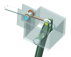 The primary alternative to water ballast for giving ULDBs the power necessary to sail well upwind and reaching is canting keel systems. The first operational canting keel yacht that I am aware of was Fiery Cross , designed and built by Jim Young after being inspired by the imaginings of L. Francis Herreshoff. The first canting keel boat I was aware of was Red Herring , designed by David Hubbard of wing sailed catamaran fame. The first production canting keel yacht was the Schock 40—designed and built in Southern California around 2000. The system has become fairly common in offshore racing boats which are focused on outright speed. Canting keel boats rely on a keel fin that is hinged at the bottom of the boat to increase the righting moment of the boat. The keel fin extends into the hull of the boat and is attached to a device (usually a hydraulic ram) which cants it relative to the hull. The maximum cant angle is usually on the order of 45 degrees each side of centerline. 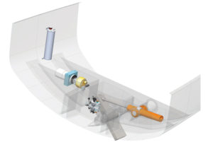 The final alternative for providing righting moment on ULDBs is the use of foils projecting from the side of the boat and configured to provide a combination of side force and lift. The lift reduces the effective displacement of the boat as well as providing righting moment. The current IMOCA solo offshore racing yachts have pushed this to the point where they are effectively flying on many points of sail. The problem with this sort of arrangement for most boats is that the lift is proportional to the square of the boat speed and most boats just don’t go fast enough to get the foil into a range of operating speeds where they are effective. Even in large high performance yachts they are not effective at providing righting moment upwind (i.e. their effect on righting moment does not compensate for their added drag). With the understandable challenges that come with side foils, we are typically left with two realistic options for making ULDBs perform well on reaches and upwind: water ballast and canting keels. Of the two options, canting keels hold the most potential, especially power reaching. On the other hand, water ballast offers relative simplicity and has the advantage that the boat is operating at a lighter weight downwind and in light air. This makes it a reasonable choice for light air and windward/leeward sailing, which is why I have gravitated towards that solution for the boats I have designed for the Pacific Northwest. From the February 2020 issue of 48° North  Paul BiekerPaul Bieker is the founder and owner of Bieker Boats, which recently relocated from Seattle to Anacortes. He has designed everything from the fastest International 14s in the world to the hulls of the most recent America’s Cup multihulls, and many things in between. Race Reports , Featured Red Ruby Project: Cowes Dinard to St. Malo RaceSeptember 27, 2024  Boat Maintenance & Repairs , Featured Cruisers College Announces Fall Lineup of Classes for Boat OwnersSeptember 26, 2024  2024 Stuart Sinclair Regatta RecapSeptember 25, 2024 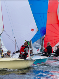 Boating Lifestyle , Featured Casting Off: Make Room for OystersSeptember 24, 2024  Boats & Gear , Featured September Products NewsSeptember 23, 2024  Great Racing and J/24 Western Regional at PSSCSeptember 20, 2024 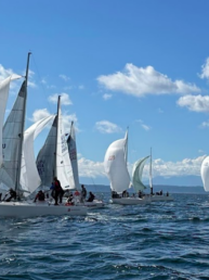
More Righting Moment Means Less Heel
Wind force on the sails causes a sailboat to heel. Resistance to heeling, called righting moment (RM), results from the lateral movement of the boat’s center of buoyancy away from the center of gravity (CG). To compare the heeling behavior of a catamaran versus a monohull, consider a 45-foot mono as having similar accommodations to those of a 40-foot cruising cat. The mono displaces 30,000 pounds, and the cat displaces 18,500 pounds. Each has about 950 square feet of sail area. The moment of force required to heel the monohull 1 degree is about 1,900 pounds-feet. The force to heel the cat the same amount is 9,200 pounds-feet, almost five times greater, because the newly immersed part of the catamaran is much farther from the CG than that part of a monohull. In general, the righting moment of a monohull increases close to linearly up to about 25 degrees of heel. The maximum RM for this boat would be about 80,000 pounds-feet at about 65 degrees of heel. For the catamaran, the RM increases linearly for the small angles of heel illustrated here. Its maximum, 142,000 pounds-feet, occurs at the point the windward hull flies, in this case at about 16 degrees of heel. The top illustration shows the two boats at rest. The middle one shows the catamaran at 1 degree of heel and the monohull subjected to the same force at 5 degrees of heel. In the bottom panel, the monohull is heeling 15 degrees–the limit of comfort for some sailor–while the cat, under a similar load, heels only 3 degrees. These numbers are approximations based on data from several boats.
 2025 Boat of the Year Nominees Announced New on the Docks: Leopard 46 Sailboat Review: Dufour 41 Pre-Owned: 1988 Hylas 47 La Paz, Mexico, Open for Charter with The Moorings Sunsail Expands Charter/Flotilla Options in Croatia and Greece The Write Stuff: Cruising World Turns 50

The PDQ 32 Cruising Cat Used Boat Review Dufour 44 Used Boat Review Blue Jacket 40 Used Boat Review Catalina 270 vs. The Beneteau First 265 Used Boat Match-Up How to Create a Bullet-Proof VHF/SSB Backup Tips From A First “Sail” on the ICW Tillerpilot Tips and Safety Cautions Best Crimpers and Strippers for Fixing Marine Electrical Connectors Revive Your Mast Like a Pro Solving the Dodger Dilemma Polyester vs. Nylon Rode Getting the Most Out of Older Sails Sailing Triteia: Budget Bluewater Cruising How To Keep Pipe Fittings Dry: Sealant and Teflon Tape TestsFuel Lift Pump: Easy DIY Diesel Fuel System Diagnostic and Repair Propane Leak: How to Detect, Locate and Fix Why Choose the Wharram Design? Winterizing: Make It Easy With Checklists Stopping Holding-tank Odors Giving Bugs the Big Goodbye Galley Gadgets for the Cruising Sailor The Rain Catcher’s Guide Sailing Gear for Kids What’s the Best Sunscreen? UV Clothing: Is It Worth the Hype? Preparing Yourself for Solo Sailing R. Tucker Thompson Tall Ship Youth Voyage On Watch: This 60-Year-Old Hinckley Pilot 35 is Also a Working… On Watch: America’s Cup On Watch: All Eyes on Europe Sail Racing Dear Readers
Measuring PerformanceWhat do the numbers tell us about seaworthiness, stability and speed.  All sailors are performance oriented. It’s only when we delve into the details that differences arise. One-design racers know that their place in the fleet hinges on tactics as well as boat speed. Those racing to Bermuda, Hawaii or even more distant landfalls, discover that a timely finish depends upon boat speed in the fog, in the middle-of-the-night and during light air interludes—not just when everyone is rolling along at hull speed. A cruiser faces a different quest. Their perspective on performance is shaped by a smaller crew members, more reliance on self-steering gear and a propensity to enjoy the ride rather than shave seconds off each mile. So, when it comes to defining your performance perspective, make sure you and your crew agree on the traffic lane in which you prefer to sail and make sure your boat aids and abets that effort. Race boat designers are innovators, and when it comes to an empirical approach to yacht design, they and their computers juggle a wide range of variables. Speed under sail isn’t the only frame of reference. At the same time they also have to contend with rating rules meant to penalize what makes a sailboat go fast. The goal is to come up with a design that favors boat speed, safety, sail-handling efficiency and creates a sailboat that’s minimally penalized by the rating rule. At times this “shaped to a rule” approach can lead to some unwanted attributes. In this overview, we will ignore the trend to design to a rating rule and look at the features that make some sailboats much better performers than others. Our version of performance is more than a singular focus on polar diagrams and boat speed. We agree that good performance needs to be realized in a wide range of wind and sea states. But we also place considerable emphasis on seaworthiness, seakindliness, ease of boat handling and crew comfort. These can be contradictory elements, and which gets most emphasis helps to define the differences among the sailboats being built today. Boat speed-related features are fairly easy to recognize. For example, most sailors have caught on to the idea that tall rigs, large sail plans and light displacement are more than a subtle promise of speed. Shorter rigs, sprouting from heavy displacement hulls are fine in windy parts of the world. But they don’t deliver much drive in light air. When a yacht broker mentions that, “you don’t need to tuck in a reef until it’s blowing over 25 knots,” take a close look at the rig and the vessels displacement. Then ask yourself if it’s not more likely that delayed sail shortening is really due to a shortfall in sail area? You can also answer the question by working out the sail-area to-displacement ratio following the details below or go online to www.tomdove.com/sailcalc/sailcalc.html . The answer gives you a good idea of the boat’s potential power under sail. Decades ago, in the heyday of the cruiser/racer, a single design stereotype defined most of the fleet. In those days, the majority of sailboats on Long Island Sound, Tampa Bay or berthed in Marina del Rey slips were white hulled sloops sporting blue mainsail covers. This was an egalitarian era when cruisers raced and racers cruised. The net result was better seamanship. Cruisers could set spinnakers and racers knew how to anchor. Today, sailboats have become more differentiated. The fast, agile, nicely fitted out cruiser/race is still around by much less common. The result is even fewer racers are going cruising. Modern race boat deck layouts make anchoring a gymnastic event and there’s little likelihood that there’s even a properly sized anchor on board. Cruisers are missing out on the seamanship development linked to racing and how it benefits sail handling while cruising. Yacht design guru Bill Lee, coined the apt phrase “Fast is Fun.” He also recognizes that too fast can be trouble and what defines the latter is often determined by the skill set of the crew. Knowing when and how to shorten sail is a talent every sailor should cultivate. Some put that lesson on hold, and that’s OK as long as they master the art of avoiding challenging situations. This is hard to do and can lead to a lot of anxiety. Plus, it also takes much of the fun out of sailing. It’s better to prepare your boat and her crew to cope with the unexpected. This begins with developing an awareness of the boundary between being reasonably powered up versus being on the edge, about to lose control. It’s not a situation enumerated by a specific boat speed, wind velocity or angle of heel. But as one crusty old Maine coast cruiser put it, ”I can’t say exactly where trouble lies, but you’ll know when you get there.” The best solution is knowing how to depower in a hurry and safely cope with reductions in sail area.  Singlehanders, along with most shorthanded crews, really value the uptick in performance they get from the right gear. It improves efficiency in reefing, setting and dousing sails. Cruisers with an aversion to performance sailing have usually been through too many fire drills. Their version of how much sail area to set is often based upon bad experiences with less than adequate gear. Today’s sailing hardware and furling systems are rugged and reliable, but they still need to be carefully maintained. The crew must also know how to operate the gear in all kinds of conditions—from a midday thunderstorm to a midnight gale.  What to look for The next time you go to a local boat show, do a little DIY performance profiling. At most shows, you’re likely to run into a full spectrum of sailboat designs. Start with the speedsters and tally up the go fast features. Sail area leads the list and with it comes lower windage, lighter weight rigging and spars—all have benefitted from better engineering and higher modulus materials. A GZ curve illustrates righting lever. The high peak represents a boat’s maximum righting arm, which is only a part of the overall stability picture.  An offshore sailboat should have a limit of positive stability (LPS) (also known as the angle of vanishing stability- AVS) of 120 degrees or more. It is this ability to recover from a deep capsize that’s like money in the bank to every offshore passagemaker.
 A growing concern among many offshore cruisers has been a trend toward increased beam, diminished draft and a reduction in ballast. Sailing a reach makes these design changes less noticeable, but as soon as you harden up, a performance shortfall comes into play. With less ballast and no one perched on the rail, excessive heel necessitates a reef. In many cases, the shallow draft keel is almost completely hidden as the leeward portion of the hull submerges. This causes the sailboat to slide sideways and every beat to windward becomes a lesson in leeway. The preference for deep draft is one thing that hasn’t changed too much among race boat designers. Centerboards, dagger boards, drop keels and can’ting keels are also in the mix. And it’s clear that there’s been a downward trend in displacement that fits into the performance-enhancing puzzle. Today, the “less is more” rule prevails. In the 1980s, a race-winning, IMS 40-footer weighed around 18,000 pounds. Now many 40 footers tip the scale at around 10,000 pounds and carry more sail area than their predecessor. The trend flips, however, when it comes to the price tags and sticker shock. It gets quite expensive to shave weight and add speed due to the need for more esoteric materials and aerospace construction skills. The bottom line is how much is it worth to you to add a few tenths of a knot?  Multihull aficionados continue to assail the logic of lead. Monohull designers are using less but locating it more strategically at the tip of a high aspect ratio foil. This lowers the CG, increasing the righting moment but greatly adds to the stress focused at the keel to hull junction. Keel failures have become enough of an issue that the ISAF Technical Committee has been looking into the problem and they are favoring recommendations that builders increase the hull laminate thickness in the area around the keel attachment. This is a good example of how performance-enhancing features must be considered in the greater context of overall vessel design and construction. Good performance is desirable, staying afloat is essential. Stability Examined Righting moment and buoyancy are forces that work together to resist the heel induced by wind pressure on the sail plan. The more sail area, the greater the heeling moment. Multihulls have very high initial stability that’s derived from their wide beam. Monohulls have less initial stability, so when sailing to windward they soon begin to heel over. However, their “ace in the hole” is a highly appreciated attribute called secondary righting moment. It’s derived from ballast and keel geometry. Multihulls might have been a side show a few decades ago, but they now hold a mainstream role in the sailboat marketplace. Like cruising monohulls, they range from comfortable houseboat like cruisers to absolute speedsters. The latter features more sail area, lighter displacement and much more clearance between the sea surface and the underside of the bridge deck. Fixed wing masts, C and T foils and all carbon construction can help to juice up the ride. However, the downside to state-of-the-art, aircraft quality carbon fiber construction, seen aboard $7.8 million Fast Forward Composites Eagle 53, can result in serious sticker shock. But the ride says it all, acceleration with the fixed-wing spar is near instantaneous. Time will tell if it’s all just too radical or a full-scale glimpse of what lies ahead. Displacement/length ratio I prefer to preview a sail in a new boat by tallying up the numbers. For example, the J/99 is a 32’ J/Boats, Inc racer/cruiser with enough Spartan accommodations below to do some fast passage making. She looked like a double-hander’s delight and with an ISO Cat A rating and the following vital signs, the performance potential is clear: 8,900 lbs. displacement 6.5 ft. draft 11.2 ft. beam 137 limit of positive stability 37 percent ballast ratio 170 D/L ratio 24.1 SA/D ratio The data indicated an excellent performer in a wide range of wind speeds and the boat lived up to expectations. For decades, naval architects and yacht designers have been putting complex as well as simple equations to good use. We’ll take a look at a few of the latter and see how they can help to put a more definitive label on specific sailboats. Displacement length ratio is a comparative tool that allows us to group sailboats into five different performance categories. The ratio itself is a non-dimensional number that defines the relationship between weight and length of a vessel. Most sailboats fall between 100 and 400 on this rating scale. At the low end reside light weight speedsters and at the high end are heavy vessels that need a lot more sail area to attain the performance of vessels toward the lower end of the scale. The D/L ratio is a handy way to empirically make boat-to-boat comparisons.  The equation used in this calculation is based on a vessel weight expressed in long tons (2,240 pounds) and the load waterline length (LWL) measured in feet. Don’t let the math bother you. It can be followed like a recipe and a calculator will insure the accuracy of your arithmetic. D/L = DLT ÷ (0.01 X LWL)3 So, let’s assume we are calculating the D/L ratio of a sailboat with a 32’LWL and 18,000 pounds of displacement:
When looking at D/L ratios, it’s important to know the trim state of the vessel when it was measured. The weight of fuel, water and a cruising payload will affect the trim. Brochures often provide “light trim” statistics, but “half trim” status is used by most designers and presents a more realistic profile. Whatever the case, make sure that the boats you compare are all in the same state of trim. The lighter the vessel, the more of an impact a sizeable payload will have. Also recognize that sailboats with no overhang and those with long overhangs skew the ratios in opposite directions. Plumb bowed, long LWL vessels earn lower ratios while long overhangs contribute to higher ratios. Sail Area/displacement ratio Sail-area/displacement ratio is a performance-linked statistic that defines potential power under sail. The comparative metrics are vessel displacement and sail area—a sailor’s rendition of an automotive horsepower-to-weight ratio. In this case, sail area is measured in square feet or meters. No attention is given to how efficient or inefficient the hull shape happens to be. In other words, it doesn’t matter if the hull shape looks like the city dock or the underbody of the first to finish in the Newport-to-Bermuda Race. As long as their displacements and working sail area are the same, so will their SA/D ratios. The value of this metric lies in its ability to depict potential power for a given displacement—another useful tool in boat-to-boat evaluations. Solving the equation does involve changing vessel weight into the volume of water it displaces. Headsail area in the formulae below refers to the working sail area or more specifically (J x I) ÷ 2 = SA (headsail). The mainsail area has become the actual square footage because the large roach (race boats) or the hollow leech (associated with in-mast furling systems) cause simple triangle area calculations to be too inaccurate. In the following calculation we look at a sailboat that displaces 18,000 pounds and has a working sail area of 750 square feet.
Ballast ratio Ballast Ratio—is a quick and easy calculation that doesn’t involve long tons or a weight-to-water volume conversion. It’s a simple comparison of weight of ballast to weight of the entire boat calculation, expressed as a percentage. B ratio = (Bwt ÷ Disp) x 100. Assume an 18,000 pound sailboat has 7,200 pounds of ballast. B#ratio = (8200 ÷ 18000) x 100 = .40 A 40 percent ballast ratio contributes to a sailboat’s secondary righting moment. How much it contributes,depends on how deep the ballast is placed. The big plus behind a substantial secondary righting moment is that it results in a very small negative portion to the boat’s stability curve. This means that the vessel is much less likely to capsize and quite able to quickly recover from a deep knock down.  Many naval architects consider a 120°-130° limit of positive (LPS) a minimum for smaller to mid-sized offshore cruising sailboats. This can be accomplished with a high ballast ratio and less draft or a lower ballast ratio and deeper draft. The latter often entails a fin and bulb or anvil shape at the very tip of the keel. These numbers aren’t SAT scores and higher isn’t better. They should be thought of as a sequel to a compass heading rather than a patient’s vital signs. For those targeting a specific type of sailing—a high latitude ocean crossing, for example—it makes sense to favor a mid-range D/L ratio and the “good performance” range of the SA/D ratio. It’s also important to take a close look at the ballast ratio in conjunction with the boat’s LPS. Those cruising summer weekends, exploring anchorages close to home, don’t need to lug along as much lead or iron and can look favorably at ballast ratios around 30 percent. However, if it’s a light to ultra-light displacement, a beamy boat with a high SA/D ratio and a shoal-draft keel, beware of a low ballast ratio. This combination means you’ll need lots of friends on the rail when it starts to blow and if you heel beyond the initial righting moment’s sweet spot (around 40-60 degrees) there’s very little secondary righting moment to prevent a knock down. Multihull sailors put all their eggs in one basket, but it’s a big basket. Extreme beam delivers immense initial stability that peaks around 10-15 degrees of heel. With this powerful heel stopping ability there’s an assumption the secondary righting moment will never be needed. Sailed appropriately, and never caught over canvassed, the initial stability does its job. However, no multihull designer or builder offers a “can’t be capsized” warranty. Avoiding that outcome is the job of the skipper and crew who must keep careful track of the sail area set, the sea state being encountered and the potential for major fluctuations in wind velocity. Wave face geometry and a changing water plane also affect capsize avoidance. It’s no surprise that the SA/D and D/L ratios of the multihulls in the charter trade are very different than the same ratios calculated for the multihulls that race to Bermuda. Sailboats, like automobiles, are designed to excel at specific jobs. Just as a Ford F-150 and a Ferrari 488 Spider have decidedly different missions, so does an Island Packet 42 Motor Sailor and a Farr 400. In between these two specialty boats lies a wide range of other sailboats that target a compromise between the two. Sailors, like the boats available, range significantly in how they prefer to spend time on the water. Hopefully, those seeking to make fast passages end up aboard a boat that can perform up to those standards. And likewise, those out to savor slower meandering and enjoy a comfortable life aboard won’t step below into a cabin lacking head room, festooned with pipe berths, and accessorized with a two burner camping stove and an unenclosed head. The same goes for performance upgrades and making decisions as to whether to invest in light wind sails or add another fuel tank to bump up range under power. Perhaps both. Contributing Editor Ralph Naranjo is the author of The Art of Seamanship . He is an adjunct lecturer at the Annapolis School of Seamanship. RELATED ARTICLES MORE FROM AUTHORThanks Ralph a well put together article with very little bias. Very impressive. Likewise to above. I’ve tried many times to lay this information out for relatively new sailboat buyers and I wish I could do it half as well as Ralph did in this article. Bravo, Matey Ralph – recheck your math and formula for SA/D… Not clear if you multiply the entire formula by 2/3 or juts the denominator – either way it does not seem to come out as you show. Last year, due to delamination and lots of water intrusion, I replaced the ‘barn door’ rudder on my ‘83 Cal 35 with a slightly shorter and more elliptically shaped rudder. There was a noticeable difference in performance and I moved up more than several places in the one race I enter every year. D/L is not a dimensionless number (it’s dimensions are are long ton / ft3), neither is SA/D (ft2/ton). Nevertheless, the numbers can be useful at least when comparing boats with similar hull shapes. Some more discussion of the impact of hull shape (i.e. impact of hard chines, impact of location of max beam, amount of buoyancy in bow & stern, etc.) would be meaningful, as (esp the french) modern cruisers and races have dramatically different shapes than 1970s or 80s cruisers and behave quite differently when compared at similar ratios. Very nice article. I think the confusion about the 2/3 factor is that the denominator is taken to the 2/3 power. So the equation for denominator is (D in pounds / 64)**2/3. I believe the ** or ^ symbol is missing. Again, good overview with excellent examples. Jim LEAVE A REPLY Cancel replyLog in to leave a comment Latest Videos A Sailboat Tour of the Exquisite Little Harbor 63 Ketch Dock and Anchor Lines – Polyester or Nylon? The Performance Sailboat from Island Packet: Blue Jacket 40 Boat Review Top 3 Winter Boat HACKS!Latest sailboat review. 
Log in or Sign upYou are using an out of date browser. It may not display this or other websites correctly. You should upgrade or use an alternative browser . How to know if a design's righting moment is enough?Discussion in ' Stability ' started by PhilippeCE , Apr 16, 2022 .
PhilippeCE Junior MemberHello all! When designing a monohull sailboat, how do you know the design has a sufficient righting moment? lets say we have a sail of 100 square feet, and the horizontal center of effort of that sail is 10 feet from the center of gravity of that boat. at 25 mph, the wind will exert 2.5 pound of force per square feet of sail so 250 lb for the whole sail. if you multiply by the lever the mast create, 10 ft, you get 2500 lb-ft of torque. should the boat have a righting moment of 2500 lb-ft to be able to withstand this sort of wind on a beam reach? as the boat heels, the force on the sail will decrease, but is there a general rule to how much righting moment a sailboat needs? AlanX Senior MemberThere was (in 2005) a couple of formulas for the minimum righting moment in one of the Australian Standards (that I no longer have). It was: Mr=1.5*B*(225*n+Dwt) (Nm) where: B was the overall beam (m) n was the maximum number of persons on board Dwt was the displacement weight (kg). And: As<Mr/128 where: As was the sail area (m^2) Also sail area is typically estimated using: As=k*Dvol^0.667 (m^2) where: k is between 15 and 22 Dvol is the displacement volume (m^3) You can estimate the Displace volume using: Dvol=Pc*LWL*BWL*DWL (m^3) where Pc (the Prismatic coefficient varies between 0.5 to 0.8, but for a sailboat the optimum is 0.63. Anyway, hope this helps AlanX @AlanX and MR is minimm righting moment? im surprised its not dependant on the sail area. The first equation based on displacement and beam (plus people hanging on the beam). The second is based on sail areas (which is just a factor). The above are simple rules or checks from the Australian Standards (circa 2005). If you want to calculate the actual moment then you need wind speed, sail area, keel and sail centroids. (If you want to get carried away, the drag coefficient of the sail would be even better.) If you want to calculate the actual righting moment then you need to map the righting moment verses heel. (Yeah, I did that too.) This is how I used them (to check the mast Z) way back then: Regards Alan I found another one for estimating the righting moment that looks like something I did: Form Righting Moment = 90%*9.81*BWL*Dwt/6 Form Righting Moment = DEGREES(ATAN(2*DWL/BWL))/90% It was obviously based on centre of buoyancy for the mid-section of a flat bottom unballasted sharpie. Here are my calcs for a sharpie based on maximum heel moment (done to 5 degree heel increments) and 16.4m^2 sail area with a 12.5kt/hr wind speed (way too low!). Clearly I had problems with freeboard and did not meet the required righting moment from the standards: Yeah, I build the boat and capsized on the first outing. Had to add ballast. Regards AlanX Ad Hoc Naval ArchitectPhilippeCE said: ↑ ...When designing a monohull sailboat, how do you know the design has a sufficient righting moment?.. Click to expand... TANSL Senior MemberIt is not the same to speak of the righting moment, which depends to a great extent on the shapes of the boat, than of the heeling moment, which depends on the external forces applied to the boat. It would be useful to clarify what the various formulas mean. PhilippeCE said: ↑ @AlanX and MR is minimm righting moment? im surprised its not dependant on the sail area. Click to expand... @AlanX thanks a lot! I was confused about what Mr and As stood for in your first post. As I understand it, the first formula is the righting moment that come from the hull shape the displacement + the number of people who can use their weight to try to right the ship. I still find it a big weird to use that formula instead of taking the maximum righting moment you get by calculating the righting moment for different heel angle, as I'm trying to calculate this for a keeled sailboat where the form stability is half the story. What I find more interesting is "required righting moment" = sail area ( in m^2 ?) * 128. which is dependent on the sail area which makes a lot of sense, although not as precise as I'd imagine something like that to be since it doesn't take into account the length of the mast(s), and maybe a couple other things that I think should matter. for the design I'm looking for it would be about 10*128, and since its a really small boat that is in the ballpark of the righting moment it would already have. @Ad Hoc Hi! What I meant by sufficient is what a naval engineer would consider sufficient. if you know the conditions in which the boat should perform well, how do you go about finding a 'sufficient' value for the righting moment. I looked at your post and well It definitely underline that it's not a simple matter. On the other hand it's true that a boat wouldn't necessarily sail well at the heel angle it has its maximum righting moment and it's something that I would like to take into account. But my question remains... I guess MR=AS*128 is simplistic, but what would be a more precise formula, if you know what conditions the boat should perform well in? I'd imagine it would take the sail area into account, the beam, the draft, the maximum wave height and possibly other things... is there such a formula or it's just impossible to approximate the necessary righting moment in a single equation? PhilippeCE said: ↑ ...... is there such a formula or it's just impossible to approximate the necessary righting moment in a single equation? Click to expand... gonzo Senior MemberAs the boat heels, the heeling force is reduced. The calculation at zero heel only takes into consideration initial stability. The maximum stability for a keel boat is usually close to 90 degrees of heel, at which angle the force on the sails is negligible. Flooding angle is often the driving constraint, since floating is the most important safety aspect of any boat. @Ad Hoc if you had to figure it out for a design, how would you do it? DCockey Senior MemberPhilippeCE said: ↑ ets say we have a sail of 100 square feet, and the horizontal center of effort of that sail is 10 feet from the center of gravity of that boat. at 25 mph, the wind will exert 2.5 pound of force per square feet of sail so 250 lb for the whole sail. if you multiply by the lever the mast create, 10 ft, you get 2500 lb-ft of torque. Click to expand... @DCockey Alright I guess I agree that you would need a bit more info to determine how you would do it. What I'm looking for is for a general keeled sailboat, not a light dinghy. PhilippeCE said: ↑ @Ad Hoc if you had to figure it out for a design, how would you do it? Click to expand...
BlueBell . . . _ _ _ . . . _ _ _Or, build it and see. Self righting possible?Trying to calculate Righting Momentminimum longitudinal righting moment areaSelf-righting hard chined boatabout self righting capacityISAF OSR Cat_0 Self-righting sailboat?self-righting life raftsMaking this boat self righting.Self-righting boats - statistics of capsizeself righting stability

NSRI EMERGENCY OPERATION CENTRE (EOC) NSRI’s 6th Offshore Rescue Craft arrives at Gqeberha The National Sea Rescue Institute’s (NSRI) sixth Offshore Rescue Craft (ORC) Rescue 6 has completed her maiden voyage from Cape Town to her home station in Gqeberha’s port of Port Elizabeth and arrived at 15h30 on 25 September 2024. Built by Two Oceans Marine in Cape Town, the ORC is designed for high performance in harsh maritime conditions. It is self-righting and purpose-built for rescue operations in extreme conditions. At 14.8m long and 4.8m wide, it can be deployed as far as 50 nautical miles from land and has an expected lifespan of at least 40 years. Rescue 6’s delivery crew, made up of NSRI Training Manager Graeme Harding as delivery coxswain, outgoing NSRI CEO Dr Cleeve Robertson, NSRI Executive Director Mark Hughes, and three Gqeberha volunteer crew members, sailed Rescue 6 from Cape Town to Mossel Bay on September 24 th and 25th, 2024. After a crew swap and refuelling at Mossel Bay on Tuesday night, she arrived at her new home in Gqeberha’s port of Port Elizabeth late on Wednesday afternoon. “The crew at Station 6 is very excited about the arrival of our new rescue boat, said Justin Erasmus, NSRI’s Gqeberha station Commander. “She is going to make a huge difference to our crew safety and the type of operations that we can safely do.” “We are still looking for a naming sponsor, so at the moment, we use her call sign Rescue 6 as her name,” said Justin. “She is a huge step up from what we are used to, and we have adjusted our training to safely and effectively crew this extremely advanced rescue vessel,” said Justin. “We will continue with the training program to ensure we are fully operational as soon as possible and ready to put to sea for rescue operations.” “Our fleet replacement program will see the entire NSRI all-weather search and rescue fleet replaced with the new vessels, allowing for increased operational capability,” said NSRI’s Capital Projects Director Mark Hughes. “Rescue 6 is the 6th vessel, four of which are entirely South African built. We have another two to build to complete this phase of the fleet replenishment,” said Mark. This world-class search and rescue vessel can carry up to 23 survivors and accommodate six volunteer rescue crew in shock-mitigating seats, allowing for high-speed operation in difficult sea conditions. “Although most rescues are coastal and inshore, an increasing number of our operations require search and rescue vessels with extended range and advanced capability in safety and technology,” said Mark. “As the only maritime rescue service operating in South African waters, we needed to make this investment to ensure all-round safety for crew and those rescued,” he said. “Station 6 Gqeberha appreciates all the effort into building Rescue 6 , and we wish to thank everyone involved. We especially want to thank NSRI’s Executive Director of Capital Projects, Mark Hughes, who has driven the ORC project from the start for the NSRI,” added Justin. Anyone interested in the naming rights of this Offshore Rescue Craft, which will be based in Gqeberha’s port of Port Elizabeth, please get in touch with Alison Smith at 082 992 1191 or email [email protected]  Help us save lives on South African waters.You may also like.  Create a lifesaving legacyIt’s never too late to write or update your will, and it’s not all that costly, even outside of National Wills Week. ...  SafeTRX app saves another lifeA relaxing paddle turned into a nerve-wracking experience for a local kayaker. Luckily, he had downloaded the SafeTRX app. ...  Rescue 6 starts sea trials ahead of Gqeberha deliveryThree years ago, the first fully South African-built Offshore Rescue Craft (ORC), launched by the National Sea Rescue Institute (NSRI), made its way to Station 17 in Hermanus. ... | |||||||||||||||||||||||||||||||||||||||||||||||||||||||||||||||||||||||||||||||||||||||||||||||||||||||||||||||||||||||||||||||||||||||||||||||||||||||||||||||||||||||||||||||||||||||||||||||||||||||||||||||||||||||||||||||||||||||||||||||||||||||||||||||
COMMENTS
The righting moment curve is a graph that shows how the righting moment changes with different angles of heel. Some factors that affect this curve are: The displacement and distribution of weight of the boat, which determine the location and movement of the CG. The hull shape and volume of the boat, which determine the location and movement of ...
The righting moment at 15 to 30 degrees of heel tells us about the boat's sail-carrying power. A large righting moment indicates a boat that can fly a lot of sail; a boat with a lower righting moment will need her sails reefed down earlier. The maximum righting arm (or righting moment), and the heel angle at that point, tells us where the boat ...
This graphic illustration of stability highlights the boat's maximum righting arm, the angle of heel at which resistance to capsize is greatest. ... one aspect of seaworthiness is how well a person can survive inside the boat in question- deeper keels make for more righting moment but also a snappy roll, for example, promoting ...
Righting moment (RM) stability curves for a 19,200-pound boat and a 28,900-pound boat with identical GZ values. Because heavier boats are inherently more stable, RM is the standard to use when comparing different boats (Data courtesy of Dave Gerr) Another thing to bear in mind when comparing boats is that not all stability curves are created equal.
Two sailboats can have the same ballast ratios with very different righting moments. If the hulls are the same, a sailboat with all its ballast in a bulb at the bottom of the keel will be stiffer than a sailboat with a long shoal-draft keel even though they may have the same ballast ratio, and their Gz curves will be quite different.
3. Calculate the righting moment of a ship given the magnitude of the righting arm. Read, interpret, and sketch a Curve of Intact Statical Stability (or Righting Arm Curve) and draw the sectional vector diagram of forces that corresponds to any point along the curve. 4. 5.
The force pushing up through the heeled center of buoyancy is equal to the displacement of the boat. A moment is just a force times a distance, so the righting moment is the righting arm times the displacement, or: RM = GZ x Disp. An 18,000-pound boat with a GZ of 0.95 feet, at 20 degrees of heel has a GZ20° of 0.95 ft., and an RM20° of 17,100
First, we multiply the load by 1.5 to approximate the rest of the righting moment beyond 30 degrees, and divide by half of your 10-foot beam. This yields a shroud load of 6,000 pounds. The overall shroud load is divided up between your shrouds. On a boat like yours with single uppers and double lowers, the uppers see about 45% of the load and ...
Righting moment curves. In Article 4-3 the curve of stability was introduced as a graph depicting righting arms at various angles of heel. This stability curve can be obtained from the cross-curves if the vessel's draft is known, and then must be corrected for the proper location of G. The latter correction is to be discussed later; assume for ...
2. As the boat heels over the vertical area of the sails presented to the wind is reduced which reduces the actual heeling force. 3. As the boat heels over the weighted keel is lifted to windward thus creating a righting moment. The more the keel is lifted to windward the more the righting moment. Heeling Moment vs Righting Moment:
Stability measurements give important hydrostatic and stability data necessary for determining elements of both performance and safety. The results of a stability test gives a boat's righting moment, vertical centre of gravity (VCG) and limit of positive stability (LPS), which with the Stability Index (SI) can help determine a boat's eligibility to enter races categorized according to the WS ...
The Righting Moment Is a Key Factor to a Sailboat's Stability. Whilst it's the righting moment that influences a sailboat's static stability, it's the dynamic stability that has the larger affect on seaworthiness. And here's what it means to us. How Boat Displacement and Sail Area Affect Performance.
Where n is the number of crew, B the breadth of the sailboat and FS freeboard in the vicinity of the mast. This gives us the righting moment induced by the crew. The righting moment that will be used throughout the entire design is the sum of the moment at 30º due to hull forms plus the one created by the crew. RM = RM30 * Displacement + δRM
The righting moment curve after the damage should have, from the first intercept to the lesser of the extent of weather tight integrity and the second intercept, a range of at least 7°. Within this range, the righting moment curve should reach a value of at least twice the wind heeling moment curve, both being measured at the same angle. ...
Righting moment at any given angle of heel is defined as the force applied at some distance from the heeled center line times the distance from the heeled centerline. For example, if it takes 200 pounds on the rail (6 feet from the centerline in this example) to heel a boat 5 degrees, the righting moment at 5 degrees is 200 x 6 = 1,200 ft-pounds.
RM. CALCULATOR. Static righting moment the boat creates at 30 degrees heel. Please fill in the values to calculate an estimated righting moment. Calculate the Righting Moment of your boat, based on Displacement and other parameters.
Aimed at small vessel users but suitable for professional mariners. Diagrams, text and animations explaining stability: from righting lever to movement of liquid in tanks - the free surface effect. Demonstrates adding weights to a vessel, heel and list. Especially recommended for RYA examination candidates.
Canting keel boats rely on a keel fin that is hinged at the bottom of the boat to increase the righting moment of the boat. The keel fin extends into the hull of the boat and is attached to a device (usually a hydraulic ram) which cants it relative to the hull. The maximum cant angle is usually on the order of 45 degrees each side of centerline.
This can be estimated with the boat's beam, ballast, draft, and displacement. You can use the righting moment and rig geometry to calculate rig loads. Seldén estimates the main reef clew force to MSL (maximum in service load)=5.5kN, the reef tack load to MSL=3.5kN (10 Newton=1 Kg f). This will be true for all three of your reef points.
In general, the righting moment of a monohull increases close to linearly up to about 25 degrees of heel. The maximum RM for this boat would be about 80,000 pounds-feet at about 65 degrees of heel. For the catamaran, the RM increases linearly for the small angles of heel illustrated here. Its maximum, 142,000 pounds-feet, occurs at the point ...
Indeed it is. Thus do not talk about Righting Moment (RM) when you end up talking about Mast design! The two are totally different. A RM is simply = Displacement x lever = ∆.GZ That is it! What you end up referring to, is how to design a Mast/rigging. To do so, a common approach is to determine - notice this, determine the RM @ 30 degrees.
A 40 percent ballast ratio contributes to a sailboat's secondary righting moment. How much it contributes,depends on how deep the ballast is placed. The big plus behind a substantial secondary righting moment is that it results in a very small negative portion to the boat's stability curve. This means that the vessel is much less likely to ...
Hello all! When designing a monohull sailboat, how do you know the design has a sufficient righting moment? lets say we have a sail of 100 square feet, and the horizontal center of effort of that sail is 10 feet from the center of gravity of that boat. at 25 mph, the wind will exert 2.5 pound of force per square feet of sail so 250 lb for the whole sail. if you multiply by the lever the mast ...
It is self-righting and purpose-built for rescue operations in extreme conditions. At 14.8m long and 4.8m wide, it can be deployed as far as 50 nautical miles from land and has an expected lifespan of at least 40 years. ... "The crew at Station 6 is very excited about the arrival of our new rescue boat, said Justin Erasmus, NSRI's Gqeberha ...